Advertisement
Table of Contents
- 1 Safety Precautions
- 2 Table of Contents
- 3 Introduction
- 4 Description, Specifications
- 5 Check List (Contents)
- 6 Installation & Electrical Requirements
- 7 Operation
- 8 Welding
- 9 Maintenance
- 10 Trouble Shooting Chart
- 11 Wire Feed Calibration
- 12 Connecting Flextig or Spool Gun
- 13 Liner Installation
- 14 Parts Breakdown - Mig Torch
- 15 Parameter Chart
- 16 Options - Flextig or Spool Gun
- Download this manual
OWNER'S MANUAL
MM350XL M.I.G. COMBINATION UNIT
CONGRATULATIONS!
YOU HAVE PURCHASED THE WORLDS FINEST
MIG WELDING SYSTEM AVAILABLE EXCLUSIVELY FROM
SNAP-ON TOOLS. THE SNAP-ON MUSCLE MIG
SYSTEM MODEL# MM350XL IS DESIGNED AND
ENGINEERED BY THE PROS FOR THE PROS.
UNDER NORMAL CARE THIS SYSTEM WILL PROVIDE
YOU WITH YEARS OF UNSURPASSED SERVICE
AND MOST IMPORTANTLY PERFORMANCE.
FOR TECH. SERVICE, CALL TOLL-FREE 1-800-232-9353.
PROVIDE MODEL & SERIAL NUMBER.
INSTALLATION
OPERATION
MAINTENANCE
Advertisement
Table of Contents

Related Manuals for Snap-On MUSCLE MIG SYSTEM MM350XL


Summary of Contents for Snap-On MUSCLE MIG SYSTEM MM350XL
- Page 1 MM350XL M.I.G. COMBINATION UNIT CONGRATULATIONS! YOU HAVE PURCHASED THE WORLDS FINEST MIG WELDING SYSTEM AVAILABLE EXCLUSIVELY FROM SNAP-ON TOOLS. THE SNAP-ON MUSCLE MIG SYSTEM MODEL# MM350XL IS DESIGNED AND ENGINEERED BY THE PROS FOR THE PROS. UNDER NORMAL CARE THIS SYSTEM WILL PROVIDE YOU WITH YEARS OF UNSURPASSED SERVICE AND MOST IMPORTANTLY PERFORMANCE.
-
Page 2: Safety Precautions
SAFETY - WELDERS SAFETY - WELDERS DANGER WARNING • Electric welding causes ultraviolet rays • Electrical shock can result from absence and weld spatter. of grounding prong. Bystanders will be exposed to ultra- Do not remove or bypass the grounding violet rays and weld spatter. -
Page 3: Table Of Contents
MANUFACTURER’S LIMITED WARRANTY This equipment is warranted against defects in materials and workmanship for a period of two years from the date of purchase. EXCEPTION: THE MIG TORCH IS WARRANTED FOR A PERIOD OF 30 DAYS FROM THE DATE OF PURCHASE. -
Page 4: Introduction
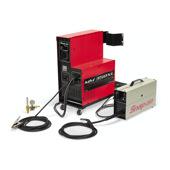
INTRODUCTION WIRE SPOOL The Snap-on Tools MM350XL is a FEED combination welding power source, ROLLS remote feed unit, MIG torch and accessory package, which is de- signed to meet the requirements of POWER SOURCE TORCH the light to heavy metal fabrica- tion industries. -
Page 5: Description, Specifications
DESCRIPTION SHORT ARC OR DIP TRANSFER (Cont.) This sequence of events is re- The MM350XL consists of a combi- peated up to 200 times per second. nation MIG welding power source and Short arc transfer is suitable for remote feed unit, a MIG torch with positional welding. -
Page 6: Check List (Contents)
CHECK LIST SPECIFICATIONS (Cont.) THE SNAP-ON TOOLS MM350XL INCLUDES WIRE TYPES: mild steel, THE FOLLOWING: stainless steel, aluminum, bronze, flux cored, 1- Combination Power Source/Remote flux cored - gasless Feed Unit. Recommended (for steel) ER70S-6 1- Dual Cylinder Rack & Industrial Wheel Kit. -
Page 7: Installation & Electrical Requirements
INSTALLATION POSITIONING THE UNIT Locate the unit adjacent to the welding area and position it so there is adequate clearance all around for ventilation and mainte- CONTACTOR SWITCH nance. CONNECT "208" WIRE FOR OPERATION ON 208 VOLT INPUT WARNING • Smoke, fumes and gases are created by the welding process. - Page 8 INSTALLING THE FEEDER CONTROL CABLE 3. With proper size wrench ASSEMBLY attach the gas fitting to the gas terminal (located on the front 1. Uncoil the cable assembly. of the feed unit). 4. Connect the control plug (female GAS HOSE pins)onto the control recep- FITTING tacle (INPUT) and tighten (lo-...
- Page 9 4. Fit the gas hose from the welding 2. Rapidly open and close the cyl- machine to the regulator outlet inder valve. This will purge fitting and tighten it with a dust and foreign matter from the wrench. Open the cylinder valve. valve.
- Page 10 FITTING AND THREADING THE ELEC- 6. Make sure the double v-groove TRODE WIRE - ALWAYS USE ER70S-6 drive roll is installed to match WELDING WIRE WHEN WELDING STEEL. the wire size. To change the wire size setting, remove the 1. Remove the wire spool clip from drive roll, turn it over and the spool hub.
- Page 11 11.Turn on the circuit breaker on 14.For steel welding only, spray the front of the machine. anti-spatter compound inside cooling fan will start and the the nozzle and on the outside of the contact tip. "ON" indicator light will illu- minate.
-
Page 12: Operation
OPERATION FITTING AND THREADING THE ELEC- TRODE WIRE (Cont.) WIRE SPOOL DRAG ADJUSTMENT The following operating instruc- tions and detailed setup procedures The center bolt of the Spool Hub enable an operator without previous Assembly is used for drag adjust- experience to produce quality fu- ment. - Page 13 PROCESS SELECTION E. CIRCUIT BREAKER Primary power switch and over- The following controls are lo- load protection device. cated on the front of the MM350XL. F. "ON" INDICATOR LIGHT Illuminates when the circuit CONTROL breaker on the machine is "ON". RECEP- TERMINAL TACLE...
-
Page 14: Welding
PROCESS SELECTION (cont.) Optimum control settings will vary according to the thickness of M. (-)NEGATIVE TERMINAL metal, type joint, Negative output terminal. operator preference, etc. Best work cable is plugged into this results can be obtained through terminal during standard weld- experience with the welding machine ing operation. - Page 15 5. Squeeze the torch trigger. The 2. Spray the inside of the nozzle wire will feed and an arc will be and the outside of the contact established. As the weld is tip with anti-spatter compound. deposited, move the torch slowly along the weld seam at a constant 3.
-
Page 16: Maintenance
MAINTENANCE OPERATING HINTS (Cont.) SPATTER To ensure that this equipment maintains operating effi- Before beginning weld ciency, the following maintenance periodically during welding, the schedule and procedures are recom- torch nozzle must be removed and the mended. These routines should be spatter (small globules of melted performed regularly by the opera- metal) cleared from the inside of... - Page 17 RECOMMENDED sity, or a fresh air supplied CUSTOMER SPARE PARTS hood should be worn. • The Snap-on Tools MM350XL is a WHEN welding near combustibles, machine of proven design and relia- a helper or "watcher" should bility. Following is a list of...
-
Page 18: Trouble Shooting Chart
TROUBLE SHOOTING (SYMBOL*) FOR TECH. SERVICE, CALL TOLL-FREE 1-800-232-9353 The Trouble Shooting Chart is a guide in identifying and correcting possible troubles which may occur when operating this equipment. FAULT POSSIBLE CAUSE REMEDY EQUIPMENT MALFUNCTION No main power, MM350XL switch is "OFF". Turn switch "on". - Page 19 TROUBLE SHOOTING (Cont.) (SYMBOL*) FOR TECH. SERVICE, CALL 1-800-232-9353 FAULT POSSIBLE CAUSE REMEDY EQUIPMENT MALFUNCTION (Cont.) Main power on, Loose torch thumb screw. Tighten thumb screw. torch Broken or loose connection. Check cables for trigger continuity. activated, Repair or tighten no welding connections.
- Page 20 TROUBLE SHOOTING (Cont.) (SYMBOL*) FOR TECH. SERVICE, CALL TOLL-FREE 1-800-232-9353 FAULT POSSIBLE CAUSE REMEDY FAULTY WELDS (Cont.) "Birdnesting" Excessive feed roll tension. Reduce tension. See page (Wire wrapping around drive Poor alignment. Make sure wire is rolls) properly aligned across roller. Oversize contact tip.
- Page 21 TESTING AND REPLACING DIODES 3. If all the diodes check out satisfactorily with the Volt- Silicon diodes have proven to be Ohm Meter, a load check must be highly reliable. However, weld made. This is easily accom- spatter build-up in the torch can plished using twelve...
-
Page 22: Wire Feed Calibration
WIRE FEED CALIBRATION Due to INPUT LINE VOLTAGE varia- tions supplied to the welding ma- chine. The WIRE FEED SPEED should be TRIM checked for proper operation. RESISTOR TO CHECK 1. Remove any tension on the drive roll. 2. Turn the wire speed dial (on the front of the machine) to "0". -
Page 23: Connecting Flextig Or Spool Gun
CONNECTING THE MHG5-B CONNECTING THE FLEXTIG SPOOL GUN CHANGING FROM STANDARD MIG OPERA- CHANGING FROM STANDARD MIG OPERA- TION TO FLEXTIG OPERATION TION TO SPOOL GUN OPERATION 1. Unplug the feeder control cable 1. Unplug the feeder control cable plug from the control receptacle plug from the control receptacle (OUTPUT)on the welder. -
Page 24: Liner Installation
M.I.G. TORCH LINER INSTALLATION GAS SEAL 3/4" (steel only) LINER The MIG torch liner provided with STICKOUT the MM350XL is designed for wire diameters from .035 thru .045. If FIG. 21. - LINER STICKOUT smaller or larger wire diameters are to be fed and or there is a Install the new liner into the problem (i.e. -
Page 25: Parts Breakdown - Mig Torch
CONSUMABLE PARTS BREAKDOWN - 35XL SERIES M.I.G. TORCH XL STYLE FRONT END - STANDARD WIRE SIZE CONTACT TIP GAS DIFFUSER NOZZLE INSULATOR .020 - .025 inch M3-T25 M6-D M6-C62 M6-B .030 inch M3-T30 (5/8" I.D.) (includes rings) 035 inch M3-T35 (1-7/16"... - Page 26 PARTS BREAKDOWN - 35XL SERIES MIG TORCH (Cont.) PART NO. DESCRIPTION (SYMBOL) TORCH NECK GROUP M3-101B ..TORCH NECK * M3-112 ..NECK INSULATOR M3-402 M3-402 M3-119 ..LOCK SCREW - SWITCH HOUSING M3-120 ..FERRULE * M3X-401 M3-200B ..SWITCH ASSEMBLY CONSISTING OF: M3-201B ..
-
Page 27: Options - Flextig Or Spool Gun
(MM140SL, MM250SL & MM350XL) The TIG Welding Process is used to produce the highest quality, porosity-free welds. The FLEXTIG adds TIG Welding capabilities to your Snap-on Tools MIG Welder. The FLEXTIG is designed for Tungsten-Inert Gas (TIG) welding with Direct Current, Straight Polarity (DCSP) on steel, stainless steel, chrome-moly, copper or cast iron (18 Ga. - Page 28 Snap-on is a trademark of Snap-on Technologies, Inc. © 2002 Snap-on Technologies, Inc. Manufactured in USA for Snap-on 2801 - 80th Street Kenosha, WI 53141-1410 ZMM350XL 6/02 (Rev. 2/03)
Need help?
Do you have a question about the MUSCLE MIG SYSTEM MM350XL and is the answer not in the manual?
Questions and answers