Table of Contents
Advertisement
Quick Links
WARRANTY.....
materials and workmanship at the date of purchase. This warranty does not cover any component parts
damaged by use or modification. In no case shall Top Flite's liability exceed the original cost of the
purchased kit. Further, Top Flite reserves the right to change or modify this warranty without notice.
In that Top Flite has no control over the final assembly or material used for final assembly, no
liability shall be assumed nor accepted for any damage resulting from the use by the user of the final
user-assembled product. By the act of using the user-assembled product the user accepts all
resulting liability.
If the buyer is not prepared to accept the liability associated with the use of this product, the
buyer is advised to immediately return this kit in new and unused condition to the place of purchase.
READ THROUGH THIS INSTRUCTION BOOK FIRST. IT CONTAINS IMPORTANT INSTRUCTIONS AND WARNINGS CONCERNING THE ASSEMBLY AND USE OF THIS MODEL.
Entire Contents © Copyright 2002
Top Flite Models guarantees this kit to be free of defects in both
Top Flite Models
P.O. Box 788
Urbana, IL 61801
Technical Assistance - Call (217) 398-8970
™
P476P03
V2.1
Advertisement
Table of Contents

Related Manuals for Top Flite P-47D THUNDERBOLT


Summary of Contents for Top Flite P-47D THUNDERBOLT
- Page 1 ™ WARRANTY..Top Flite Models guarantees this kit to be free of defects in both materials and workmanship at the date of purchase. This warranty does not cover any component parts damaged by use or modification. In no case shall Top Flite’s liability exceed the original cost of the purchased kit.
-
Page 2: Table Of Contents
TABLE OF CONTENTS Introduction ............3 Razorback ............16 Balance the airplane Laterally ......46 About the airfoils..........3 Bubble Canopy..........17 Finishing ............46 Precautions............3 Glue the stabilizer and fin to the fuselage ... 18 Covering ............46 Complete The Fuse Top Razorback ....19 Recommended Covering Sequence....47 Decisions you must make early in the building Complete The Fuse Top Bubble Canopy ..20 Apply the decals ..........47... -
Page 3: Introduction
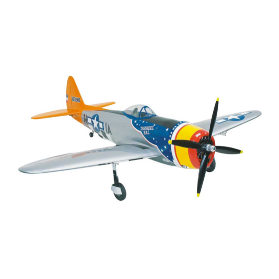
PROTECT YOUR MODEL, INTRODUCTION Dave set out to develop a list of parameters; things such as... stall speed, root chord, tip chord YOURSELF & OTHERS – FOLLOW and thickness, while making sure there would be Thank you for purchasing the Top Flite GOLD THIS IMPORTANT SAFETY adequate room for retracts, compatibility with flaps, EDITION P-47 Thunderbolt. -
Page 4: Decisions You Must Make Early In The Building Process
5. You must test the operation of the model A .61-size Schnurle-ported engine will also provide to install retracts, there are the two types – wire- before the first and each successive flight to plenty of power for your P-47 – especially if mostly and-coil or rigid struts with an oleo. -
Page 5: Top Flite Scale Accessories
OTHER ITEMS REQUIRED TOP FLITE SCALE ACCESSORIES NOTES FOR THE COMPETITION- MINDED MODELERS AND Item numbers (GPMQ4130) are suggested part SCALE COCKPIT INTERIOR: Another exciting DEVIATIONS FROM SCALE numbers recognized by distributors and hobby option made specifically for your Top Flite Gold shops and are listed for your ordering Edition P-47 is the Scale Cockpit Interior. -
Page 6: Suggested Supplies And Tools
Robart #650 Straight Robostruts – ROBQ1700 Single Edge Razor Blades – HCAR0312 (optional) Razor Saw Robart #189Air Restrictor Set – ROBQ2389 Common pliers (optional) Screwdrivers (Phillips and flat head) -or- Robart Super Stand – ROBQ1401 Century Jet Models Retracts On our workbench, we have four 11" Great T-Pins –... -
Page 7: Die-Cut Patterns Page
- 7 -... - Page 8 - 8 -...
-
Page 9: Common Abbreviations Used In The Book And On The Plans
COMMON ABBREVIATIONS USED IN TYPES OF WOOD: BUILD THE TAIL SURFACES THIS BOOK AND ON THE PLANS: BUILD THE STABILIZER AND ELEVATORS Deg = Degrees Fuse = Fuselage 1. Always build on a flat surface. Refer to the LE = Leading Edge (front) plans to identify the parts and their locations. - Page 10 LE. Glue both TE’s to all the ribs then glue the rest of the ribs to the LE. 8. Use thick CA to glue the TE joiner to the TE’s making sure the jig tabs on the ribs are contacting the building board. Wipe away HOW TO MAKE WING AND excess glue between the TE’s.
- Page 11 16. Glue the die-cut 1/8" balsa Elevator Leading Edges to the notches in the ribs then 13. Be certain you can remove the stab from the glue the bottom elevator skins in position. Note: building board after you glued the skins on. Apply Be sure the LE’s are parallel to the stab TE.
- Page 12 LE Cap 22. Glue a 3/16" x 1" x 11-7/8" balsa Leading Edge Cap to each elevator LE then trim to match the length of the elevator LE. Use a razor plane, then a sanding block to blend the top and bottom of the leading edge cap to the skins.
-
Page 13: Build The Fin And Rudder
27. Glue the shaped 7/8" thick balsa Elevator 31. Hold the bent 1/8" Elevator Joiner Wire up 34. Glue the elevator horn block to the elevator, Root Blocks to the elevators then use a razor to the elevators and mark the location of the holes then sand it so the pieces blend together. - Page 14 12. Glue the left rudder skin to the ribs and leading edge of the rudder. 8. Make a skin for each side of the fin using the 4. Cover the rudder and vertical fin portion of the 1/16" balsa sheet left over from the stab skins. plans with waxed paper.
-
Page 15: Build The Fuselage
Now you have a couple of nicely finished, lightweight, yet strong “tail feathers”. That’s pretty much the way the rest of the P-47 builds; rather “matter-of-factly.” Before you know, it you’ll have a beautifully-constructed piece of workmanship to admire. 3. Drill a 1/16" hole in the five engine mount BUILD THE FUSELAGE alignment punch marks in FWA and a 1/8"... -
Page 16: Razorback
NOTE: From this point on you will encounter a few areas on the structure that may be difficult to glue because they are not easily accessible. At this early stage much of the structure only needs to be tack glued, but it can be reinforced with thick or medium CA after the sheeting is applied and the frame is removed from the building board. -
Page 17: Bubble Canopy
BUBBLE CANOPY VERSION: Perform steps 14 and 15 if building the Bubble Canopy version. 12. Use a drafting triangle to hold the formers vertical and remove any twists as you glue one 3/16" x 3/16" x 42" balsa stringer in F-1 through 16. -
Page 18: Glue The Stabilizer And Fin To The Fuselage
GLUE THE STABILIZER AND FIN TO 2. Wet the outside surface of a sheet and test fit THE FUSELAGE it to the fuselage. Hint: a 50:50 mixture of water and rubbing alcohol applied to the outside surface will make the sheeting easier to bend. Make adjustments to the sheet if required. -
Page 19: Complete The Fuse Top Razorback
COMPLETE THE FUSE TOP RAZORBACK VERSION: Perform steps 8 through 13 only if you are building the Razorback version. 10. Cut the notch in the top of the sheet so it will However, if you are installing the optional cockpit fit against the Razor Spine and fuselage spine. -
Page 20: Complete The Fuse Top Bubble Canopy
COMPLETE THE FUSE TOP BUBBLE CANOPY VERSION: Perform steps 8-10 only if building the Bubble Canopy version. 4. Apply HobbyLite balsa filler around the fairings to blend them to the fuselage sheeting. 15. Wet the outside of an upper forward fuselage Apply a couple of thin layers and sand between top to soften it, then place it on the upper forward each application. -
Page 21: Final Steps Before Framing The Lower Fuse
FINAL STEPS BEFORE FRAMING FRAME THE FUSE BOTTOM THE LOWER FUSE 1. Drill 3/16" holes through the punch marks in formers 4-B and 5-B. 1. Turn the fuselage over and reinforce all glue joints that don’t look strong or that you couldn’t reach before. -
Page 22: Tail Gear Installation
SILVER SOLDERING Use this process when soldering metal to metal, such as brass tube to wire, or pushrod ends to wire. 9. Test fit the die-cut 3/32" balsa Wing Saddles A. Thoroughly clean the items to be soldered with 5. After carefully aligning the holes, glue both to the formers, then glue them in position. - Page 23 7. Cut two 3" long sticks from one of the 20. Thread a Nylon Clevis onto the .074" x 12" approximately 6" long scrap pieces of 3/16" x pushrod then place it over the Aft Rudder Pushrod 3/16" stringers leftover from the top of the drawn on the plans and cut it 1/8"...
-
Page 24: Fit The Intercooler Air Exits
3. Hold an air exit up to the side stringer, then use a ball-point pen to mark where the side stringer interferes with it. Use a razor saw to carefully cut through the side stringer and sheeting. Remove this piece from the fuselage. 24. -
Page 25: Sheet The Fuse Bottom
3. Use a sanding block and 150-grit sandpaper to blend the stringers to the formers and eliminate any glue blobs or irregularities. Even up the stringer ends with the formers. 7. Bend the sheet into contact with the aft stringer then wick thin CA into the joint–from the 7. -
Page 26: Install The Engine
available the P-47 will have a tendency to climb as 11. Trim the ends of the aft bottom sheeting full power is applied. This condition can be even with F-9 and F-5D. controlled by adding an additional one degree of down thrust to the engine. -
Page 27: Install Servo Tray
7. After the epoxy cures, remove the C-clamps FUSELAGE CONSTRUCTION NOTES: and apply a fillet of 30-minute epoxy on both sides of F-1 all the way around the tank roof and tank floor and the right and left crutches. Make sure the crutches are glued to the tank roof and floors as well. -
Page 28: Build The Wing
BUILD THE WING 5. Ribs W-2 through W-6 have punch marks just aft of the spar. Drill a 3/16" hole at each of these marks for future installation of the aileron pushrods. NOTE: The wing panels are built “UPSIDE- DOWN” on the plans. The jig tabs are attached to what is, in the end, the TOP surface of the wing. -
Page 29: Build The Wing Panels
and the notches in the die-cut 1/8" balsa Aft Outer Spar to account for the forward sweep of the spar. Test fit but do not glue the aft outer spar in ribs W-7 through W-11. Fit but do not glue the die-cut 3/32"... - Page 30 10. Hold the dihedral gauge near the middle of W-1 and lightly tack glue the rib to the top and 15. Skip this step if you are NOT going to 13. Glue a die-cut 1/8" plywood Dowel Plate bottom main spars. Do not glue the dowel plate build the optional flaps.
- Page 31 Proceed to step 25 if you will be installing retractable landing gear. 21. Test fit a 1/2" x 3/4" x 6-3/4" grooved Landing Gear Rail into the notches in ribs W-4, W-5, and W-6. The fit should be snug and the FOR RETRACT GEAR ONLY groove should be facing away from the work surface.
- Page 32 elevator construction) to mark the bevel line and aileron skin to the rest of the ribs. Leave the shim wheels will retract fully into the wheel well. With the rib end line on the inside surfaces of the skins, in place until the wing is removed from the the CJM retracts and the modifications to the rib then sand the bevel just as you did for the elevator building board.
-
Page 33: Join The Wing Panels
JOIN THE WING PANELS 4. Test fit the wing bolt plate into each wing panel. Make adjustments if necessary. 6. When you have confirmed that all parts fit 1. Cut away the portion of rib W-1 behind the well, disassemble the pieces. Coat the dihedral dowel plate and 1/16"... -
Page 34: Preparations Before Adding Bottom Wing Sheeting
PREPARATIONS BEFORE ADDING All balsa sheeting will usually bend when it’s BOTTOM WING SHEETING cut from the log since stresses are relieved. For the best results, trim the edges of the wing sheeting with a long metal straightedge and a sharp knife 1. -
Page 35: Prepare The Wing For The Top Sheeting
NOTE: The steps below show the sheeting of a Hint: The best balsa filler, is no balsa filler! Take with a Clevis Retainer on the horn end and a wing with functioning flaps. Wings without flaps are your time fitting all sheeting and skins in place. Nylon Faslink on the bellcrank end. - Page 36 12. If you will be installing fixed landing gear, use the same technique to locate the position of the LG blocks. Push a pin through the sheeting at each end of the grooved block, then drill a 3/16" hole through the sheeting at the location of the LG block.
-
Page 37: Sheet The Top Of The Wing
SHEET THE TOP OF THE WING The top of the wing will be sheeted in four sections like the bottom of the wing. 1. Temporarily reinstall the 1/4" wing dowels in the wing. Locate the die-cut 1/8" plywood Leading 21. Make the cutouts in the bottom wing skin Edge Jigs, Trailing Edge Jigs (A) and (B), and the for the retracts. -
Page 38: Build The Flaps
BUILD THE FLAPS 6. Join each strip of wood trimmed off the upper forward skins to each of the remaining two 6" x 30" 1. Remember the pin hole you made in the sheets to make the Upper Aft Skins. Trim the upper flap skin? Insert a pin through this hole, upper aft skins to fit the wing. -
Page 39: Fit The Flaps
will see the punch marks in the ribs that can be 8. Remove the plywood flap horn and tack 12. Reinforce the underside of the wing used as a guideline as well. Reference the cross glue the other, shorter flap LE in position. sheeting (where it overhangs the aft inner spar at sections of the wing plans. -
Page 40: Build The Ailerons
plans. When the base fits, apply glue only to the 4. Insert three #309 Robart Super Hinge side and the top of the base and then Points into the wing but do not glue them in permanently glue it in position. until after the wing and the flaps are covered. -
Page 41: Mount The Wing To The Fuse
MOUNT THE WING TO THE FUSE 12. Complete the sheeting of the wing by filling any spaces that have not been sheeted with left over 1/16" balsa – areas such as the aft center 1. Trim the fuselage sheeting until it accurately matches the contour of the balsa wing saddles. -
Page 42: Build The Wing Fillet
3. Trial fit a 1/32" plywood Wing Fillet Base on the wing saddle of the fuselage. Make adjustments if required. Use a hobby knife with a #11 blade to lightly scribe a line on the fillet base from the corner where it meets the rear of the fuselage out to the edge–cut only through the bottom layer of the three-ply plywood. -
Page 43: Build The Wing Belly Pan
4. Place two more 3/16" stringers in the notches from 5-E to F-1 then glue the stringers to all the formers except 2-C. 14. Now the fun part! Get out the balsa filler 11. (Optional) Use the template on the plans to (Hobbico HobbyLite recommended) and begin make two sets of wing fillet braces from left over 1/8"... -
Page 44: Sheet The Belly Pan
Insert the tubes in the wing, trace a line on them using the sheeting as a guide then cut the tubes to the approximate beveled shape. Glue the tubes to the belly pan side sheet and the wing sheeting. Be careful not to get any glue on the heads of the nylon wing bolts and accidentally glue the bolts to the tubes or wing bolt plate. -
Page 45: Build And Fit The Cowl
9. Use balsa filler to build up a small fillet 3. Carefully wick thin CA around the joints and between the belly pan and the wing and fill any allow the parts to cure. Do not use CA other gaps between the sections of belly pan accelerator. -
Page 46: Finish Preparation
top wing skins in the wheel wells. This will fuelproof and reinforce the exposed wood inside the wheel well. This must be done before the covering is applied as it may blemish the covering. BALANCE THE AIRPLANE LATERALLY SPECIAL NOTE: Do not confuse this procedure with “checking the C.G.”... -
Page 47: Recommended Covering Sequence
Cover the aircraft with MonoKote film using the Recommended Covering Sequence: sequence below. Make sure the MonoKote film is 1. Tail fillet strips thoroughly bonded to the structure and all of the 2. Rudder left side edges are sealed. Use a Top Flite MonoKote Hot 3. -
Page 48: Apply Panel Lines To The Model
APPLY PANEL LINES TO THE MODEL PAINTING 3. Test fit the elevators to the stabilizer with all of (OPTIONAL) the hinges and the wire joiner in place. Make sure the trailing edge of both elevators are even. Make We recommend Top Flite LustreKote for Panel lines are easy to apply and enhance the adjustments to the joiner wire if necessary. -
Page 49: Final Assembly
2. Hookup and adjust the flap linkages. Two .074 x 4" Threaded End Rods and Nylon Clevises are supplied to make the flap pushrods. The flap pushrods are connected to the servos using Nylon Faslinks. Refer to the Control Surface Throws section for recommended travel. 3. -
Page 50: Cockpit Finishing
COCKPIT FINISHING OPTIONAL COCKPIT INTERIOR (Basic cockpit) 1. Cut out the existing cockpit floor (if you haven’t already done so) and test the unfinished pieces of your Top Flite Cockpit Interior (Not 1. Sand the inside of the cockpit with 320-grit included –... -
Page 51: Install Receiver, Switch And Battery
INSTALL RECEIVER, SWITCH AND BATTERY CONTROL SURFACE THROWS 1. After connecting the servos and switch harness to the receiver, wrap it and the battery with 1/4"-1/2" foam rubber to protect them from vibration. We recommend the following control surface throws: 2. -
Page 52: Balance Your Model
BALANCE YOUR MODEL GROUND CHECK THE MODEL 3. Lift the model at the balance point. If the tail If you are not thoroughly familiar with the drops when you lift, the model is “tail heavy” and operation of R/C models, ask an experienced you must add weight* to the nose to balance. -
Page 53: Ama Safety Code
Keep your face and body as well as all full scale aircraft. Where necessary an observer FLYING spectators away from the plane of rotation of the shall be used to supervise flying to avoid having propeller as you start and run the engine. models fly in the proximity of full scale aircraft. -
Page 54: Flying
Full flaps make the Thunderbolt very steady in CAUTION (THIS APPLIES TO ALL R/C the landing pattern, but carry a little extra power to AIRPLANES): If, while flying, you notice any make up for the extra drag. The extra drag of the unusual sounds, such as a low-pitched “buzz,”... - Page 55 Remove shaded area for Century Jet Models retract units. - 55 -...
-
Page 56: Three-View Drawing
THREE-VIEW DRAWING Use this layout for trim scheme planning only. Not suitable for scale documentation.
Need help?
Do you have a question about the P-47D THUNDERBOLT and is the answer not in the manual?
Questions and answers