Table of Contents
Advertisement
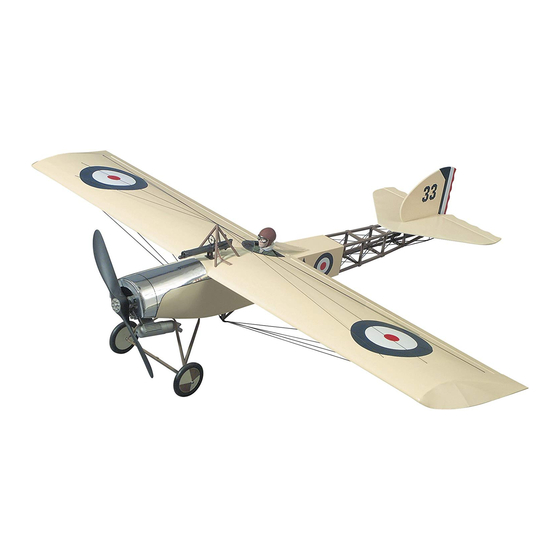
65 in [1650mm]
Wingspan:
778 sq in [50.2 dm²]
Wing Area:
5.5 – 7.0 lbs [2500 - 3182g]
Weight:
Wing Loading:
16 – 21 oz/sq ft
[50–64 g/dm²]
49.5 in [1257mm]
Length:
WARRANTY.....
not cover any component parts damaged by use or modification. In no case shall Top Flite's liability exceed the original cost of the purchased kit. Further, Top Flite reserves
the right to change or modify this warranty without notice. In that Top Flite has no control over the final assembly or material used for final assembly, no liability shall be assumed
nor accepted for any damage resulting from the use by the user of the final user-assembled product. By the act of using the user-assembled product the user accepts all
resulting liability. If the buyer is not prepared to accept the liability associated with the use of this product, the buyer is advised to immediately return this kit in new
and unused condition to the place of purchase.
Top Flite Models 3002 N. Apollo Dr., Suite 1, Champaign, IL 61822
READ THROUGH THIS INSTRUCTION BOOK FIRST. IT CONTAINS IMPORTANT INSTRUCTIONS AND WARNINGS CONCERNING THE ASSEMBLY AND USE OF THIS MODEL.
Entire Contents © Hobbico, Inc 2012
Top Flite Models guarantees this kit to be free of defects in both material and workmanship at the date of purchase. This warranty does
Technical Assistance Call (217)398-8970 productsupport@top-flite.com
™
ELD4P03 for TOPA0215 V1.1
Advertisement
Table of Contents

Related Manuals for Top Flite Elder 40


Summary of Contents for Top Flite Elder 40
- Page 1 In no case shall Top Flite‘s liability exceed the original cost of the purchased kit. Further, Top Flite reserves the right to change or modify this warranty without notice. In that Top Flite has no control over the final assembly or material used for final assembly, no liability shall be assumed nor accepted for any damage resulting from the use by the user of the final user-assembled product.
-
Page 2: Table Of Contents
Tail Wheel Wire Installation ....26 Flite Elder. The Top Flite Elder is a classic design from FINAL CONSTRUCTION....27 the early years of modeling, brought back by requests 6. -
Page 3: Additional Items Required
Top Flite Elder. Order numbers are sure to provide the full kit name (Top Flite Elder) ❏ Sanding tools and sandpaper assortment (see provided in parentheses. and the part numbers as listed in the Parts List. -
Page 4: Important Building Notes
Sanders and replaceable Easy-Touch Adhesive- pen (not a felt tip pen) to lightly write the name or backed Sandpaper. While building the Top Flite size on each piece so you can identify it later. Use Elder, we used two 5-1/2" Bar Sanders and two 11"... -
Page 5: Common Abbreviations
numbers stamped on them, but in some cases the COMMON ABBREVIATIONS METRIC CONVERSIONS number is located alongside the parts or only on the 1" = 25.4mm (conversion factor) die drawings in the manual. Do not remove the die-cut deg. = Degrees parts until instructed to do so. -
Page 6: Die-Cut Patterns
DIE-CUT PATTERNS - 6 -... -
Page 7: Build The Tail Surfaces
BUILD THE TAIL SURFACES Build the Elevator ❏ 1. From the 1/4" x 1-3/4" x 36" [6 x 32 x 914mm] Build the Stab balsa sheet, cut two pieces 10-1/2" [267mm] in length. ❏ 1. Tape the Wing/Stab Plan view to your building board. - Page 8 Trial fit the hinge into the slot. If the hinge does not slide in easily, work the knife back and forth in the slot a few times to provide more clearance (it is really the back edge of the blade that does the work here in widening the slot).
-
Page 9: Build The Fin And Rudder
Build the Fin and Rudder BUILD THE WING Frame the Wing ❏ ❏ 1. Tape the Right Wing Plan view to your building board. Cover the plan with Plan Protector. ❏ ❏ 2. Locate one of the shaped balsa leading edges and one of the shaped balsa trailing edges. - Page 10 ❏ ❏ ❏ ❏ 7. Test fit the W2 rib at the end of the basswood spar. 12. Glue each of the remaining ribs to the shaped balsa leading edge, centering them as you go. ❏ ❏ 16. Locate one of the 3/32" x 1" x 30" [2.4 x 25 x ❏...
-
Page 11: Install The Wing Joiners
Install the Wing Joiners Important! The following steps are for the right wing panel. ❏ ❏ ❏ 19. Place the sheeting flat on the bench and 4. When you are satisfied with the fit of each sand the joints of the sheeting smooth on the side brace, glue them in place with 30-minute epoxy. -
Page 12: Finish The Bottom Of The Wing
❏ ❏ Finish the Bottom of the Wing 5. On the wing plan there are four locations shown for 3/8” x 3/8” [9.5 x9.5mm] basswood blocks. ❏ ❏ 1. For the right wing panel, locate a 3/32" x The blocks are provided in the kit and are cut to the 1-1/8"... -
Page 13: Join The Wings
Join the Wings Now that both of the wing panels are joined, go back to the section, “Finish the Bottom of the Wing”. ❏ 1. Glue the die-cut 1/8" [3mm] ply sub spar dowel Follow the instructions to finish the bottom of the left brace to the balsa sub spars on the left wing panel wing the same way you did the right wing. -
Page 14: Build The Aileron
it in place. Do Not Glue the front 1-1/4" [32mm] of Build the Aileron the tip to the wing. Proceed to the next step after the glue has completely cured. ❏ ❏ 6. Carefully bend the tip of the wingtip on the score until the tip takes on the contour of the wing. -
Page 15: Finish The Wing
❏ ❏ 6. Sand the aileron to its final shape as shown on the cross section of the wing. Sand a “V” in the leading edge. ❏ 7. Repeat steps 1-6 for building the aileron for the left wing. Finish the Wing ❏... -
Page 16: Build The Fuselage
BUILD THE FUSELAGE Frame the Fuselage Notice that you are building the right side first. ❏ 1. Tape the Fuselage Plan side view to your building board. Cover the plan with Plan Protector. Build the right fuselage side first. ❏ ❏ 6. - Page 17 ❏ ❏ 11. Glue one of the 48-3/4" [1239mm] basswood ❏ 14. This completes the right side of the fuselage. longerons to the top of the right fuse side as shown Now is a good time to sand the side of the fuselage on the plan.
- Page 18 FOR STEPS 22-27 USE THE TOP VIEW OF THE FUSELAGE PLAN AS AN AID IN KEEPING THE FUSELAGE STRAIGHT. ❏ ❏ 18. The firewall has eight punch marks. Draw two 20. Locate the firewall mounting gauge. This reference lines for mounting the engine to the firewall gauge will set the proper amount of right thrust as shown.
- Page 19 ❏ 28. Glue the 1/16" [1.6mm] tail gusset in place at the rear, bottom of the fuselage with 6-minute epoxy. ❏ ❏ 24. From the 1/8" x 3" x 24" [3 x 76 x 610mm] 26. Cut and glue the remaining cross braces in balsa, sheet the bottom of the fuselage.
-
Page 20: Mount The Wing To The Fuselage
❏ Mount the Wing to the Fuselage 32. Earlier you temporarily glued F3T and F4T in place. Remove and discard them. ❏ 3. Measure from the tip of the left wingtip to the tail of the fuselage and from the right wingtip to the tail of ❏... -
Page 21: Finish The Fuselage
extending 3/8" [9.5mm] out of the wing leading edge. drilling be sure that the drill remains perpendicular to Wipe any excess glue from the exposed dowel. Allow the top of the wing. If the drill does not remain the glue to cure then round the ends of the dowels as perpendicular to the wing you may not hit the center of shown on the plan. - Page 22 ❏ washers and four #6 lock washers. Temporarily place 7. Locate the two die-cut 1/8" [3mm] plywood nose your engine in the mount to set the width of the rings. Glue them together to form one 1/4" [6mm] mounting rails to fit your engine. Remove the engine plywood nose ring.
-
Page 23: Adding The Wing Fairing
❏ ❏ 15. Cut two more pieces of sheeting long enough to fit from the fuselage side to the front of the nose ring. Bevel the sheeting Cut one of the sheets to a width of 1-1/2" [38mm] (save where it contacts the the remaining half of the sheeting to be used when fuselage side. -
Page 24: Assemble And Install The Landing Gear
❏ Assemble and Install the Landing Gear 3. From left over 3/32" x 3" [2.4 x 76mm] balsa sheeting cut two pieces to a length of 3-1/2". ❏ 1. Locate the two prebent wire landing gear wires and one of the coils of wrapping wire. Make a wire wrapped joint at each end and the middle of the main landing gear wire where shown on the plan. - Page 25 E. To get a good bond between the soft wrap wire and the wire landing gear it is important to use a good solder and flux. The Great Planes® Silver ❏ ❏ 2. After completing the three solder joints on the 5.
-
Page 26: Tailskid Installation
Tailskid Installation ❏ 6. Locate the pre-bent wire tail skid. Wrap and solder it together in the three locations shown on the plan. Once the solder has cooled, bend the end of the wire to a slight angle as shown on the plan. ❏... -
Page 27: Final Construction
❏ FINAL CONSTRUCTION Install the Radio 5. Cut the 11-3/4" [298mm] gray outer plastic pushrod guide to a length of 9". Use sandpaper to Mount the Engine roughen one end of the 9" plastic tube. Insert the smooth end of the tube through the firewall back into the radio compartment. -
Page 28: Finishing
3. Use a large brush, air pressure or a Top Flite Tack stab; and a Trim Iron for small areas. tube in the firewall. Feed the wire into the tube until Cloth (TOPR2185) to remove dust from the model. -
Page 29: Installing The Stab And Fin
90 degrees to to paint or stain the open structure of the fuselage. the stab. When you are satisfied with the fit and Ours was painted with Top Flite LustreKote ® paint. If... -
Page 30: Join The Control Surfaces
Join the Control Surfaces The following steps are used only if you are using a tail wheel. ❏ 6. Trial fit the hinges and the tail wheel wire into the rudder. Trial fit the rudder to the stab inserting the hinges into the hinge slots and the nylon tail wheel bearing into the slot in the fuselage cross bracing. -
Page 31: Install The Elevator And Rudder Pushrods And Control Horns
❏ Install the Elevator, Rudder Pushrods 8. Reference the plan to locate the position for the and Control Horns nylon control horn on the bottom of the elevator. Mark the location for the screw holes for the control ❏ horn. Drill a 3/32" [2.4mm] hole through the elevator 1. -
Page 32: Install The Aileron Pushrods & Control Horns
Install the Aileron Pushrods and Scale Details Cotter pin Control Horns Looking at the photo on the box you will see that we added a few extra details to our model. They are not necessary for any structural integrity but we felt they added a bit of nostalgic detail that you might want to consider adding to your model. -
Page 33: Final Hookups And Checks
cord towards the center of the fuselage. Join the left and right wing wires by inserting a #2 sheet metal screw into the two landing gear straps and then screwing them into the kingpost. ❏ ❏ 5. Turn the wing over and locate the 1/16" [1.6mm] holes in each of the blocks in the bottom wing. -
Page 34: Control Throws
❏ CONTROL THROWS 5. Make sure the control surfaces move in the proper direction as illustrated in the following sketch. High rate Low Rate Aileron 3/8" [9.5mm] Up 1/4" [6mm] Up 3/8" [9.5mm] Down 1/4" [6mm] Down Elevator 5/8" [16mm] Up 7/16"... -
Page 35: Preflight
If the PREFLIGHT control surfaces do not respond correctly, do not fly! We use a Top Flite Precision Magnetic Prop Balancer” Find and correct the problem first. Look for loose (TOPQ5700) in the workshop and keep a Great... -
Page 36: Engine Safety Precautions
❏ ❏ Use a chicken stick or electric starter and follow the 3. Secure the battery and receiver with a strip 20. Balance your propeller (and spare propellers). ❏ instructions to start your engine. of balsa or plywood. Simply stuffing them into 21. -
Page 37: Flying
FLYING more forgiving than asphalt when landing in a crosswind. The Top Flite Elder is a great flying sport plane that flies smoothly at all flying speeds. Though the plane Good luck and have a great time flying! has a nostalgic “slow fly” look to it, it is capable of performing mild aerobatics as well. - Page 38 - 38 -...
- Page 39 - 39 -...
Need help?
Do you have a question about the Elder 40 and is the answer not in the manual?
Questions and answers