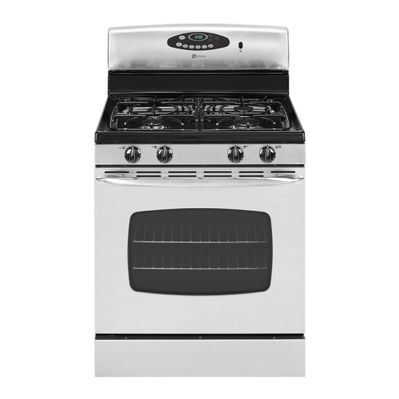
Maytag AGR5715QD Service Manual

Maytag AGR5715QD Service Manual

Gas freestanding range
Hide thumbs Also See for AGR5715QD:

Advertisement

Service
This manual is to be used by qualified appliance
technicians only. Maytag does not assume any
responsibility for property damage or personal
injury for improper service procedures done by
an unqualified person.
Gas
Freestanding
Range
This Base Manual covers general information
Refer to individual Technical Sheet
for information on specific models
This manual includes, but is
not limited to the following:
AGR5715QD*
AGR5735QD*
AGR5835QD*
JGR8775QD*
JGR8875QD*
MGR5754QD*
MGR5755QD*
MGR5765QD*
MGR5775QD*
MGR5875QD*
16022498
Revision 0
November 2003

Advertisement

Table of Contents
loading

Summary of Contents for Maytag AGR5715QD

  • Page 1 Service This manual is to be used by qualified appliance technicians only. Maytag does not assume any This Base Manual covers general information responsibility for property damage or personal Refer to individual Technical Sheet injury for improper service procedures done by an unqualified person.
  • Page 2: Important Information

    Important Notices for Servicers and Consumers Maytag will not be responsible for personal injury or property damage from improper service procedures. Pride and workmanship go into every product to provide our customers with quality products. It is possible, however, that during its lifetime a product may require service.
  • Page 3: Table Of Contents

    LP Gas Surface Burner Orifice Configuration ..A-4 Natural Gas Surface Burner Orifice Configuration .. A-5 Converting Bake Burner Orifice ......A-6 Converting Broil Burner Orifice ......A-8 Low Flow Conversion For Surface Burner Valves ... A-9 16022498 Rev. 0 ©2003 Maytag Appliances Company...
  • Page 4 14 inches W.C.P. WARNING To avoid risk of electrical shock, property damage, personal injury or death; verify wiring is correct, if components were replaced. Verify proper and complete operation of unit after servicing. 16022498 Rev. 0 ©2003 Maytag Appliances Company...
  • Page 5: Safety Information

    Electrical Code. Do not use an extension cord with this appliance. • Insure all packing materials are removed from the range before operating it, to prevent fire or smoke damage should the packing material ignite. 16022498 Rev. 0 ©2003 Maytag Appliances Company...
  • Page 6: Oven

    Do not let a potholder touch the flame. Do not use a towel or a bulky cloth as a potholder. • Never leave range unattended while cooking. Boilovers can cause smoking and may ignite. 16022498 Rev. 0 ©2003 Maytag Appliances Company...
  • Page 7: Baking, Broiling, And Roasting

    These items may ignite causing a fire. CAUTION Do not store items of interest to children in cabinets above range. Children may climb on oven to reach these items and become seriously injured. 16022498 Rev. 0 ©2003 Maytag Appliances Company...
  • Page 8: Electrical Requirements

    Larger slot on adapter must be aligned with larger slot in the wall receptacle to provide proper polarity. 16022498 Rev. 0 ©2003 Maytag Appliances Company...
  • Page 9: Product Safety Devices

    If any ground wire, screw, strap, nut, etc. is removed for service, or any reason, it must be reconnected to its original position with original fastener before the appliance is put into operation again. Failure to do so can create a possible shock hazard. 16022498 Rev. 0 ©2003 Maytag Appliances Company...
  • Page 10: General Information

    Eyelevel Range Grill Range (20") Feature Content Range (36") 1000-3999 Brands Drop In (24") 4000-6999 Maytag/Amana Wall Oven (27") 7000-9999 Jenn-Air Range, Free-Standing (30") Slide-In (30") Range Hood Wall Oven RV Range RV Top 16022498 Rev. 0 ©2003 Maytag Appliances Company...
  • Page 11: Rating Label

    Therefore, 120 VAC should never be applied directly to to bend. the oven valve terminals. The glow bar is the power source for the oven valve. 16022498 Rev. 0 ©2003 Maytag Appliances Company...
  • Page 12: Specifications

    • For product in Canada call 1-866-587-2002 or visit the Web Site at www.amana.com Web Sites at www.amana.com or www.maytag.com or • For Maytag product call 1-800-688-9900 or visit the www.jennair.com Web Site at www.maytag.com • For Jenn-Air product call 1-800-536-6247 or visit the Extended Service Plan Web Site at www.jennair.com...
  • Page 13: Troubleshooting Procedures

    • Check 120 VAC to ignitor, if no No voltage from control ....... No oven operation in bake or broil. voltage, replace control. • Verify all connections are clean Loose wire connection or broken wire..and tight, replace broken wire. 16022498 Rev. 0 ©2003 Maytag Appliances Company...
  • Page 14 Fan motor does not operate. next step. Failed fan motor or winding or frozen shaft. • Check motor winding for continuity. Check for a frozen motor shaft. Check for broken wiring between motor and neutral terminal block. 16022498 Rev. 0 ©2003 Maytag Appliances Company...
  • Page 15 Oven smokes/odor first few usage. times of usage • Ventilate area well and perform self-clean cycle. • See Testing Procedures for Electronically Controlled......Failure Codes diagnostic checks. 16022498 Rev. 0 ©2003 Maytag Appliances Company...
  • Page 16: Testing Procedures

    Measure continuity at the following points: Terminal to terminal......Continuity Terminal to ground ......Infinite Approximately 14 Ω - cold Convection element Test continuity of terminals....Test voltage to terminals ....120 VAC 16022498 Rev. 0 ©2003 Maytag Appliances Company...
  • Page 17 Switch in LITE position ....... Continuity Switch in any other position....Infinite Top surface burner Verify gas is supplied ......Check for obstructions in burner ports. Verify burner cap is positioned correctly. 16022498 Rev. 0 ©2003 Maytag Appliances Company...
  • Page 18 7 & 14 Continuity Convect 10 & 11 Continuity Clean 10 & 12 Continuity Keep Warm 4 & 7 Continuity Favorites 10 & 15 Continuity Timer 12 & 13 Continuity Light 12 & 15 Continuity 16022498 Rev. 0 ©2003 Maytag Appliances Company...
  • Page 19 Continuity CV Roast 7 & 11 Continuity Clean 7 & 15 Continuity Keep Warm 11 & 12 Continuity Favorites 13 & 14 Continuity Timer 5 & 11 Continuity Light 7 & 13 Continuity 16022498 Rev. 0 ©2003 Maytag Appliances Company...
  • Page 20: H1 Control

    See “Quick Test Mode”. The last 5 diagnostic codes will be stored Display in the non-volatile memory. Cycle through the codes using the number pads 1 through 5. See “Description of Error Codes” for explanation. 16022498 Rev. 0 ©2003 Maytag Appliances Company...
  • Page 21 – Control specific Diagnostic Code Display Mode can be activated by pressing and holding the AUTOSET pad for 3 seconds at power-up. Diagnostic Code Display Mode can only be started while powering up the control. 16022498 Rev. 0 ©2003 Maytag Appliances Company...
  • Page 22 LOCK flashes Disables Clean and Lockout functions LOCK flashes Disables Clean and Lockout functions 9d31 Latch both locked and unlocked LOCK flashes Disables Clean and Lockout functions 9d32 Latch both locked and unlocked 16022498 Rev. 0 ©2003 Maytag Appliances Company...
  • Page 23 If the control is in a known good lock position and the unlock switch becomes faulted: • The control will not fault. • After the function is canceled and unlock is attempted, the control will attempt to unlock the latch according to the procedures in these notes. 16022498 Rev. 0 ©2003 Maytag Appliances Company...
  • Page 24: M1 Control

    The last 5 diagnostic codes will be stored Display Power Up the unit. in the non-volatile memory. Cycle through the codes using the See “Description of Error Codes” for number pads 1 through 5. explanation. 16022498 Rev. 0 ©2003 Maytag Appliances Company...
  • Page 25: M2 Control

    The last 5 diagnostic codes will be stored Display Power Up the unit. in the non-volatile memory. Cycle through the codes using the See “Description of Error Codes” for number pads 1 through 5. explanation. 16022498 Rev. 0 ©2003 Maytag Appliances Company...
  • Page 26 – Control specific Diagnostic Code Display Mode can be activated by pressing and holding the AUTOSET pad for 3 seconds at power-up. Diagnostic Code Display Mode can only be started while powering up the control. 16022498 Rev. 0 ©2003 Maytag Appliances Company...
  • Page 27 Disables Clean and Lockout LOCK flashes functions 9d21 Unlock switch not closed Disables Clean and Lockout LOCK flashes functions 9d31 Lock and unlock switches both closed Disables Clean and Lockout LOCK flashes functions 16022498 Rev. 0 ©2003 Maytag Appliances Company...
  • Page 28 If the control is in a known good lock position and the unlock switch becomes faulted: • The control will not fault. • After the function is canceled and unlock is attempted, the control will attempt to unlock the latch according to the procedures in these notes. 16022498 Rev. 0 ©2003 Maytag Appliances Company...
  • Page 29: Disassembly Procedures

    7. Once the control panel bottom edges are free, pull control panel forward and raise the control panel upward to release screws securing top back edges and allow control panel to tip forward. 8. Reverse procedure to reinstall control panel. 16022498 Rev. 0 ©2003 Maytag Appliances Company...
  • Page 30: Oven Sensor

    3. Remove screws securing spark module to unit the oven cavity. chassis. 10.Remove screws securing ignitor to bake burner. 4. Replace and reverse procedure to reassemble. 11. Replace and reassemble in reverse order. 16022498 Rev. 0 ©2003 Maytag Appliances Company...
  • Page 31: Door Plunger Light Switch

    5. Remove screws securing top and back of side panel. 6. Pull rear of side panel away from range then slide side panel forward to release from side panel spacers. 7. Reverse procedure to reinstall side panel. 16022498 Rev. 0 ©2003 Maytag Appliances Company...
  • Page 32: Storage Drawer Track Removal

    2. Disconnect gas and power cord from unit. related problems. 3. Remove storage drawer. 4. Disconnect power cord plug located behind storage drawer. 5. Remove screw securing cord to unit. 6. Replace and reassemble in reverse order. 16022498 Rev. 0 ©2003 Maytag Appliances Company...
  • Page 33 Frameless Oven Door Door linning Glass frame Inner glass Door baffle Inner Door door hinge glass Insulation trim Side Door trim handle bracket Door glass retainer Tape Side Door trim handle Bottom trim Door glass 16022498 Rev. 0 ©2003 Maytag Appliances Company...
  • Page 34 Appendix A 16022498 A – 1 ©2003 Maytag Appliances Company...
  • Page 35: Appendix A Gas Conversion

    Replace plastic cover over cap. See *$6 35(6685( 5(*8/$725 figure 4. /2&$7(' $7 %27720 2) 7+( 5($5 2) 7+( 5$1*( 7851 &/2&.:,6( 3/$67,& &29(5 72 ,167$// ),*85(  ),*85(  UNMNmRVUJSM (07-03-00) A – 2 16022498 ©2003 Maytag Appliances Company...
  • Page 36 When orifice change is complete, remove two screws then re-install burner head and secure with same two screws. g. Replace the burner caps and grates using caution when replacing each burner cap so that electrode is not damaged. 16022498 A – 3 ©2003 Maytag Appliances Company...
  • Page 37 Gas Conversion A – 4 16022498 ©2003 Maytag Appliances Company...
  • Page 38 Gas Conversion 16022498 A – 5 ©2003 Maytag Appliances Company...
  • Page 39 See figure 3. cfdrob N OVEN BOTTOM MUST CLEAR THIS EDGE IN ORDER TO BE REMOVED OPENING IN BAKE CHAMBER SCREW cfdrob O cfdrob P A – 6 16022498 ©2003 Maytag Appliances Company...
  • Page 40 BAKE ORIFICE LP BAKE ORIFICE IS LOCATED IN THE LP CONVERSION KIT AND IS STAMPED WITH NUMBERS “.049”. VIEWING THE BAKE ORIFICE AFTER THE REMOVAL OF THE STORAGE DRAWER cfdrob Q 16022498 A – 7 ©2003 Maytag Appliances Company...
  • Page 41 N BROIL ORIFICE TURN COUNTER CLOCKWISE TO REMOVE. LP BROIL ORIFICE IS LOCATED IN THE LP CONVERSION KIT AND HAS #57 AND GREEN INDICATOR MARK ON ITS SIDE. cfdrob O A – 8 16022498 ©2003 Maytag Appliances Company...
  • Page 42 ),*85(  HOLD VALVE STEM IN “LOW” POSITION WHILE MAKING SCREW ADJUSTMENT FOR GAS CONVERSION TURN ADJUSTMENT SCREW ABOUT 1/4 OF A TURN TO ADJUST FOR LP GAS ),*85(  16022498 A – 9 ©2003 Maytag Appliances Company...

Table of Contents