Falcon Nexus 110 User's Manual & Installation Instructions
Dual fuel
Hide thumbs
Also See for Nexus 110:
- User's manual & installation instructions (52 pages) ,
- User's manual & installation instructions (52 pages) ,
- User's manual & installation instructions (56 pages)
Table of Contents
Advertisement
Advertisement
Table of Contents

Related Manuals for Falcon Nexus 110


Summary of Contents for Falcon Nexus 110
- Page 1 USER GUIDE & INSTALLATION INSTRUCTIONS Nexus 110 Dual Fuel...
- Page 2 SLOW BAKED LEG OF LAMB METHOD 1. Preheat the oven to 220 ¡C (for a conventional oven), 200 ¡C (for a fan oven) or gas mark 7. 2. Pull the small sprigs off the rosemary branches and set aside with the garlic. 2.
-
Page 3: Table Of Contents
Technical Data Cooking Tips Tips on Cooking with the Timer General Oven Tips Cooking Table Cleaning Your Cooker Essential Information Hotplate Burners Ceramic Hotplate The Griddle Glide-out Grill™ Control Panel and Doors Ovens Cleaning Table Nexus 110 Dual Fuel U110323-01... -
Page 5: Before You Start
1. Before You Start... If you smell gas Your cooker should give you many years of trouble-free cooking if installed and operated correctly. It is important • DO NOT turn electric switches on or off. that you read this section before you start, particularly if you •... - Page 6 Accessible parts will become hot during use and will Fig.1-1 retain heat even after you have stopped cooking. Keep babies and children away from the cooker and never wear loose-fitting or hanging clothes when using the appliance. Always be certain that the controls are in the OFF position ArtNo.324-0001 Steam burst when the oven is not in use, and before attempting to clean the cooker.
-
Page 7: Cooker Care
WARNING! DO NOT place anything between the base of the pan Unattended cooking on a hob with fat or oil can be and the heating zone surface (e.g. asbestos mats, dangerous and may result in fire. aluminium foil, wok cradle). NEVER leave a chip pan unattended. -
Page 8: Cooker Overview
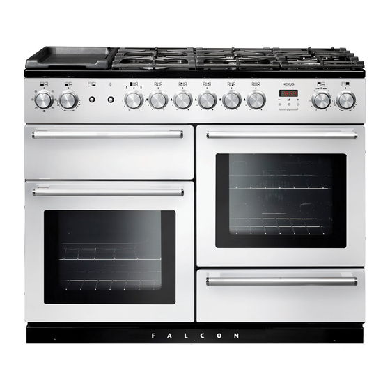
2. Cooker Overview Fig.2-1 The 110 dual fuel cooker (Fig.2-1) has the following features: Fig.2-2 4 hotplate burners, a Wok Burner and a Ceramic Multizone hotplate Control Panel Glide-out Grill™ with 4 position Trivet Multifunction Oven Fan Oven Bread Proving/Storage Drawer Hotplate Burners The labels by each of the control knobs indicates which area that knob controls. -
Page 9: Wok Burner
The igniter should spark and light the gas. Continue to press Fig.2-3 in the knob to let the gas through to the burner for about ten seconds. If and when you let go of the control knob or the burner goes out, then the FSD has not been bypassed. -
Page 10: The Ceramic Hotplate
The Ceramic Hotplate Fig.2-11 The hotplate area on the left-hand side is dual purpose. It can be used either as a ceramic hob to heat a pan in the usual way (Fig.2-11) or it can be used to heat the supplied griddle. The rear area, marked with a ring, is for cooking with a pan. -
Page 11: The Griddle
The Griddle Fig.2-16 The griddle (Fig.2-17) is designed to fit securely on the locating pins over the ceramic heating area (Fig.2-18). DO NOT try to use it over one of the gas burners. It will not be securely held and you may damage the non-stick finish. To heat the whole area, turn the hotplate control clockwise (Fig.2-19). -
Page 12: The Glide-Out Grill
The Glide-out Grill™ Fig.2-21 Open the door and pull the grill pan carriage forward using the handle (Fig.2-21). The grill has two elements that allow either the whole area of the pan to be heated or just the right-hand half. Adjust the heat to suit by turning the control knob. -
Page 13: Bread Proving Drawer
Bread Proving Drawer Fig.2-24 The Bread Proving Drawer is found on the right at the base of the cooker (Fig.2-24). Within the Bread Proving Drawer there are slots in the base to allow warmed air to flow through into the drawer from the element underneath. The Bread Proving Drawer temperature is ideal for proving all sorts of yeast dough from sweet to savoury, gluten free to sourdough, dough made from fresh yeast and dried,... -
Page 14: The Ovens
The Ovens Multifunction Oven Functions The clock must be set to the time of day before the ovens Fan Oven will work. See the following section on ‘The Clock’ for This function operates the fan and the heating instructions on setting the time of day. element around it. - Page 15 The exposed top element may cook some foods too quickly, so we recommend that the food be positioned in the lower Fig.2-26 half of the oven to cook. The oven temperature may also need to be lowered. Browning Element This function uses the element in the top of the oven only.
-
Page 16: Using The Clock
Operating the Ovens Fig.2-29 Operating the Multifunction Oven The multifunction oven has two controls: a function selector and a temperature setting knob (Fig.2-26). Turn the function selector control to a cooking function. Turn ArtNo.306-0001 - 3-button clock the oven temperature knob to the temperature required (Fig.2-27). - Page 17 Re-set the Minute Minder Fig.2-35 To re-set the minute minder, first select the minute minder program by pressing the mode [M] button. Then press the [+] and [-] buttons simultaneously. • The ‘cook period’, which is the length of time you ArtNo.306-0001 - 3-button clock want the oven to cook for (dur).
-
Page 18: Accessories
Accessories Fig.2-40 Oven Shelves Flat shelf Shelf guard In addition to the flat shelves, your cooker is supplied with a drop shelf (Fig.2-40). The drop shelf increases the possibilities for oven shelf spacing. The oven shelves can be easily removed and refitted. Front Pull the shelf forward until the back of the shelf is stopped by the shelf stop bumps in the oven sides (Fig.2-41). -
Page 19: Cooking Tips
3. Cooking Tips Tips on Cooking with the Timer General Oven Tips If you want to cook more than one dish, choose dishes that The wire shelves should always be pushed firmly to the back require approximately the same cooking time. However, of the oven. -
Page 20: Cooking Table
4. Cooking Table DocNo.031-0004 - Cooking table - electric & fan single cavity The oven control settings and cooking times given in the table below are intended to be used Top (T) AS A GUIDE ONLY. Individual tastes may require the temperature to be altered to provide a preferred result. -
Page 21: Cleaning Your Cooker
5. Cleaning Your Cooker Essential Information Fig.5-1 Isolate the electricity supply before carrying out any thorough cleaning. Allow the cooker to cool. NEVER use paint solvents, washing soda, caustic cleaners, biological powders, bleach, chlorine based bleach cleaners, coarse abrasives or salt. DO NOT mix different cleaning products –... -
Page 22: Ceramic Hotplate
Ceramic Hotplate Fig.5-5 Daily Care First of all, be sure that the heat indicator light is off and that the cooking surface is cool. Apply a small dab of ceramic cleaning cream in the centre of the area to be cleaned. Dampen a clean paper towel and work the cream onto the cooking surface. -
Page 23: Glide-Out Grill
Glide-out Grill™ Fig.5-6 The grill pan and trivet should be washed in hot soapy water. Alternatively, the grill pan can be washed in a dishwasher. After grilling meats or any foods that soil, leave to soak for a few minutes immediately after use. Stubborn particles may be removed from the trivet using a nylon brush. -
Page 24: Control Panel And Doors
Control Panel and Doors Fig.5-10 Avoid using any abrasive cleaners, including cream cleaners. For best results, use a liquid detergent. The same cleaner can be used on the doors, or alternatively, using a soft cloth wrung out in clean hot soapy water – but take care that no surplus water seeps into the appliance. -
Page 25: Cleaning Table
Cleaning Table Cleaners listed (Table 5-1) are available from supermarkets or electrical retailers as stated. For enamelled surfaces use a cleaner that is approved for use on vitreous enamel. Regular cleaning is recommended. For easier cleaning, wipe up any spillages immediately. Hotplate Part Finish... -
Page 26: Troubleshooting
6. Troubleshooting Hotplate ignition or hotplate burners faulty If there is an installation problem and I don’t get my original installer to come back to fix it who pays? Is the power on? Is the clock illuminated? You do. Service organizations will charge for their call If not, there maybe something wrong with the power outs if they are correcting work carried out by your supply. - Page 27 The timed oven is not coming on when automatic cooking Fig.6-1 Has the oven knob been left in the OFF position by mistake? Is the oven locked (see above)? ArtNo.324-0005 Oven light bulb Oven temperature getting hotter as the cooker gets older If turning the temperature down using the oven control knob has not worked, or has only worked for a short time, then you may need a new thermostat.
-
Page 28: Installation
INSTALLATION Check the appliance is electrically safe and gas sound when you have finished. 7. Installation Dear Installer Provision of Ventilation Before you start your installation, please complete the details This appliance is not connected to a combustion products below, so that, if your customer has a problem relating to evacuation device. - Page 29 INSTALLATION Check the appliance is electrically safe and gas sound when you have finished. You will need the following equipment to complete the Checking the parts: cooker installation satisfactorily: 3 pan supports Wok cradle • Stability bracket: If the cooker is to be supplied with gas through a flexible hose, a stability bracket or chain MUST be fitted.
-
Page 30: Positioning The Cooker
INSTALLATION Check the appliance is electrically safe and gas sound when you have finished. Positioning the Cooker Fig.7-1 Fig.7-1 and Fig.7-2 shows the minimum recommended 75 mm 75 mm distance from the cooker to nearby surfaces. 650 mm The cooker should not be placed on a base. The hotplate surround should be level with, or above, any adjacent work surface. -
Page 31: Moving The Cooker
INSTALLATION Check the appliance is electrically safe and gas sound when you have finished. Moving the Cooker Fig.7-5 On no account try and move the cooker while it is plugged into the electricity supply. The cooker is very heavy, so take great care. We recommend that two people manoeuvre the cooker. -
Page 32: Fitting The Stability Bracket Or Chain
INSTALLATION Check the appliance is electrically safe and gas sound when you have finished. Fitting the Stability Bracket or Chain Fig.7-9 Stability bracket Unless otherwise stated, a cooker using a flexible gas connector must be secured with a suitable stability device. Suitable stability devices are shown in Fig.7-8, Fig.7-9 and Cooker Fig.7-10. -
Page 33: Gas Connection
INSTALLATION Check the appliance is electrically safe and gas sound when you have finished. Gas Connection Fig.7-11 This must be in accordance with the relevant standards. The flexible hose (not supplied with the cooker) must be in accordance with the relevant standards. Hoses may be purchased at most builders’... -
Page 34: Electrical Connection
INSTALLATION Check the appliance is electrically safe and gas sound when you have finished. Electrical Connection Fig.7-12 This appliance must be installed by a suitably qualified electrician to comply with the relevant electrical regulations, and also the local electricity supply company requirements. Current Operated Earth Leakage Breakers The combined use of your induction cooker and other domestic appliances may cause nuisance tripping, so we... -
Page 35: Final Checks
INSTALLATION Check the appliance is electrically safe and gas sound when you have finished. Final Checks Fig.7-14 Hob Check Check each cooking zone in turn. Be sure to use pans of the correct size and material. Grill Check Turn on the grill control and check that the grill heats up. Oven Check Set the clock as described earlier, and then turn on the ovens. -
Page 36: Circuit Diagram
8. Circuit Diagram P095199 P095199 P095199 1.1kW 1.1kW P028728 P095199 P095199 P095199 The connections shown in the circuit diagram are for single-phase. The ratings are for 230 V 50 Hz. Code Description Code Description Code Colour Grill front switch Right-hand fan oven thermostat Blue Grill energy regulator Right-hand fan oven control... -
Page 37: Technical Data
DocNo.107-0023 - Technical data - 110DF - Classic DL 9. Technical Data THE COOKER IS CATEGORY: Cat II 2H3+ ; Cat II 2E+3+ ; Cat II 2L3B/P ; Cat II 2E3B/P ; Cat II 2H3B/P ; Cat II 2ELL3B/P . It is supplied set for group H natural gas. - Page 40 Clarence Street, Royal Leamington Spa, Warwickshire, CV31 2AD, England. Tel: +44 (0) 1926 457400 Fax: +44 (0) 1926 450526 E-mail: consumers@falconappliances.co.uk...
Need help?
Do you have a question about the Nexus 110 and is the answer not in the manual?
Questions and answers