Table of Contents
Advertisement
Quick Links
Advertisement
Table of Contents

Related Manuals for Falcon Nexus 90 Dual Fuel


Summary of Contents for Falcon Nexus 90 Dual Fuel
- Page 1 USER GUIDE & INSTALLATION INSTRUCTIONS Nexus 90 Dual Fuel Australia U111292 - 04...
-
Page 3: Table Of Contents
Contents Before You Start... Troubleshooting Personal Safety Service and Spares Electrical Connection Safety 10. Installation If You Smell Gas Peculiar Smells Safety Requirements and Regulations Cooling Fan Provision of Ventilation Ventilation Location of Cooker Maintenance Conversion Grill/Glide-out Grill™ Care Positioning the Cooker Cooker Care Moving the Cooker Cleaning... -
Page 5: Before You Start
Before You Start... DO NOT operate with panels, covers or Your cooker should give you many years of • trouble-free cooking if installed and operated guards removed from this appliance. correctly. It is important that you read this The cooker should not be placed on a base. •... -
Page 6: Electrical Connection Safety
DO NOT use a steam cleaner on your Check the appliance is gas sound after • cooker. completion. Always keep combustible materials, e.g. Make sure that the gas supply is turned • • curtains, and flammable liquids a safe on and that the cooker is wired in and distance away from the cooker. -
Page 7: Ventilation
the grill or ovens are in operation the fan will by the manufacturer of the cooking run to cool the fascia and control knobs. appliance or indicated by the manufacturer of the appliance in the instructions for use Ventilation as suitable or hob guards incorporated in the appliance. - Page 8 along the back of the cooker) for warming Fig. 1.1 plates, dishes, drying tea towels or softening butter. DO NOT use water on grease fires and • never pick up a flaming pan. Turn the ArtNo.324-0001 Steam burst controls off and then smother a flaming pan on a surface unit by covering the pan completely with a well fitting lid or baking tray.
-
Page 9: Grill/Glide-Out Grill™ Care
door glass since they can scratch the underneath it, otherwise the knobs may surface, which may result in shattering of become hot. the glass. NEVER close the grill door when the grill is • Make sure the shelves are pushed firmly •... - Page 10 Before you remove any of the grill parts for • cleaning, make sure that they are cool or use oven gloves. DO NOT use any abrasive substances on • the grill and grill parts. DO NOT put the side runners in a •...
-
Page 11: Cooker Overview
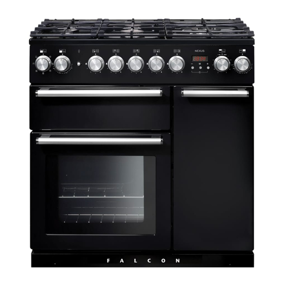
Cooker Overview Fig. 2.1 The 90 dual fuel cooker (Fig. 2.1) has the following features: Fig. 2.2 A. 4 hotplate burners and a Wok Burner B. Control Panel C. Glide-out Grill™ with 4 position Trivet D. Multifunction Oven E. Fan Oven Hotplate Burners The labels by each of the control knobs indicates which area that knob controls. -
Page 12: Wok Burner
If and when you let go of the control knob or the burner goes Fig. 2.3 out, then the FSD has not been bypassed. Turn the control knob to the OFF position and wait for one minute before you try again, this time making sure to hold in the control knob for slightly longer. -
Page 13: The Griddle Plate
The Griddle Plate Fig. 2.12 The griddle plate fits the left-hand pan support, front to back (Fig. 2.12). It is designed for cooking food on directly. DO NOT use pans of any kind on it. The griddle plate surface is non-stick and metal cooking utensils (e.g. spatulas) will damage the surface. -
Page 14: The Ovens
The Ovens Function The clock must be set to the time of day before the left hand Defrost To thaw small items in the oven without heat oven will work. See the following section on ‘The Clock’ for instructions on setting the time of day. A full cooking function, even heat throughout, Fan oven great for baking... -
Page 15: Multifunction Oven Functions
Multifunction Oven Functions Fan Assisted Oven This function operates the fan, circulating air heated Defrost by the elements at the top and the base of the oven. The combination of fan and conventional cooking This function operates the fan to circulate cold air (top and base heat) makes this function ideal for cooking only. -
Page 16: Fan Oven
Fan Oven Fig. 2.17 The right-hand oven is a fan oven that circulates hot air continuously, which means faster, more even cooking. The recommended cooking temperatures for a fan oven are generally lower than a conventional oven. Note: Please remember that all cookers vary so temperatures in your new ovens may differ to those in your previous cooker. - Page 17 To remove the glide-out runners Fig. 2.22 Twist to unclip the base of the runners from the shelf Front supports. Then unhook the runner from the top rung of the bracket shelf support and remove (Fig. 2.23). Rear stop To refit the glide-out runners Hook the rear of the runner over the top rung of a pair of shelf supports.
-
Page 18: Using The Glide-Out Grill
Using the Glide-out Grill™ DocAUS.020-0004 - Overview - 110DF - Elan Fig. 3.2 Fig. 3.1 Nearest to the element Middle High Middle Low Furthest from the element Four grill height positions refer to Fig. 3.5 Fig. 3.4 Fig. 3.3 To switch on both elements To switch on the right half element Four grill height positions Fig. -
Page 19: Button Clock
3 button clock Setting the time Reset the minute minder The clock must be set to the time of day before the oven will Note: The cook work. symbol [ ] remains visible during normal operation. ArtNo.306-0001 - 3-button clock ArtNo.306-0001 - 3-button clock Press the [+] and [-] buttons simultaneously. - Page 20 To Automatically Start & Stop the Oven AUTO is showing, but you want to revert (main oven only) to manual cooking (main oven only) Press [M] button Press either [+] or again until current [-] buttons time is diplayed. ArtNo.306-0001 - 3-button clock ArtNo.306-0001 - 3-button clock Changing the frequency of the alarm Set the length of...
-
Page 21: Cooking Table
Cooking Table The oven control settings and cooking times given in the table below are intended to be used as a Top (T) guide only. Individual tastes may require the temperature to be altered to provide a preferred result. ArtNo.050-0007 Centre (C) Oven shelf positions Food is cooked at lower temperature in a fan oven than in a conventional oven. -
Page 22: Cleaning Your Cooker
Cleaning your cooker Essential Information Fig. 7.1 Isolate the electricity supply before carrying out any thorough cleaning. Allow the cooker to cool. NEVER use paint solvents, washing soda, caustic cleaners, biological powders, bleach, chlorine based bleach cleaners, coarse abrasives or salt. DO NOT mix different cleaning products –... -
Page 23: The Griddle Plate
The Griddle Plate Fig. 7.5 Always clean the griddle plate after use. Allow it to cool completely before removing. Immerse the griddle plate in hot soapy water. Use a soft cloth or, for stubborn stains, a nylon washing up brush. NOTE: If the griddle plate is washed in a dishwasher then some dishwasher residue may appear on the back. -
Page 24: Ovens
Glass Fronted Door Panels Fig. 7.9 The oven door front panels can be taken off so that the glass panels can be cleaned. Move the cooker forward to gain access to the sides (see the ‘Moving the Cooker’ section under ‘Installation’). -
Page 25: Cleaning Table
Cleaning table Cleaners listed are available from supermarkets or electrical retailers as stated. For enamelled surfaces use a cleaner that is approved for use on vitreous enamel. Regular cleaning is recommended. For easier cleaning, wipe up any spillages immediately. Hotplate Part Finish Recommended Cleaning Method... -
Page 26: Troubleshooting
Troubleshooting Hotplate/Cooktop ignition or hotplate burners faulty Food is cooking too slowly, too quickly, or burning Is the power on? Is the clock illuminated? Cooking times may differ from your previous oven. If not, there maybe something wrong with the power supply. Check that you are using the recommended temperatures and shelf positions –... - Page 27 Oven light is not working Fig. 8.1 The bulb has probably burnt out. You can buy a replacement bulb (which is not covered under the warranty) from a good electrical shop. Ask for a 40 W - 230 V halogen lamp (G9) (Fig. 8.1). Turn off the power at the circuit breaker.
-
Page 28: Service And Spares
INSTALLATION Check the appliance is electrically safe when you have finished. Service and Spares Firstly, please complete the appliance details below and keep them safe for future reference – this information will enable us to accurately identify the particular appliance and help us to help you. Filling this in now will save time and inconvenience if you later have a problem with the appliance. -
Page 29: 10. Installation
The regulations and standards are as follows: installation kit available from the vinyl-wrap supplier. Falcon cannot accept any responsibility for damage caused due to • AS/NZS 5601 – ‘Gas Installations’... - Page 30 INSTALLATION Check the appliance is gas sound when you have finished. 3 pan supports Wok cradle (Supplied) Small pan trivet ArtNo.000-0009 Wok ring, cast ArtNo.000-0001 90 Pan supports Griddle plate (Supplied) Teppanyaki (optional) You will need the following equipment to complete the cooker installation satisfactorily: •...
-
Page 31: Positioning The Cooker
INSTALLATION Check the appliance is gas sound when you have finished. Positioning the Cooker Fig. 10.1 The diagram (Fig. 10.1) shows the minimum recommended distance from the cooker to nearby surfaces as given in AS/NZS 5601. *Any splashback must be fitted in accordance with the manufacturers instructions. -
Page 32: Moving The Cooker
INSTALLATION Check the appliance is gas sound when you have finished. be possible to move the cooker in and out for cleaning and Fig. 10.3 servicing. Moving the Cooker On no account try and move the cooker while it is plugged into the electricity supply. -
Page 33: Repositioning The Cooker Following Connection
INSTALLATION Check the appliance is gas sound when you have finished. Fitting a Stability Bracket Fig. 10.7 When fitting a stability bracket (Fig. 10.7) please refer to the instructions supplied with the bracket for further details on fitting. When fitting a stability bracket (Fig. 10.8 and Fig. 10.9) adjust the bracket to give the smallest practicable clearance Alternative positions between the bracket and the engagement slot in the rear of... -
Page 34: Gas Connection
INSTALLATION Check the appliance is gas sound when you have finished. Gas Connection Fig. 10.11 This must be in accordance with the relevant standards. The gas supply needs to terminate with a down-facing Gas inlet threaded fitting ½” connection. The inlet connector is located just below the hotplate level at the rear of the cooker. -
Page 35: Electrical Connection
INSTALLATION Check the appliance is gas sound when you have finished. Electrical Connection Current Operated Earth Leakage Breakers This appliance must be installed by a qualified electrician The combined use of your cooker and other domestic to comply with with current AS/NZS 3000 Wiring Rules and appliances may cause nuisance tripping, so we recommend regulations in force. -
Page 36: Fixed Wiring
INSTALLATION Check the appliance is gas sound when you have finished. Fixed Wiring Fig. 10.14 Disconnect from the mains supply. For connection to fixed wiring, i.e. flexible conduit, Remove the electrical terminal cover on the back panel (Fig. 10.14). Remove the M4 screw securing the reducer plates to the conduit box (Fig. -
Page 37: Final Fitting And Checks
INSTALLATION Check the appliance is gas sound when you have finished. Final Fitting and Checks Fig. 10.19 Hob Check Check each cooking zone in turn. Be sure to use pans of the correct size and material. Grill Check Turn on the grill control and check that the grill heats up. Oven Check x 2 positions Set the clock as described earlier, and then turn on the ovens. -
Page 38: 11. Servicing
WARNING – SERVICING TO BE CARRIED OUT ONLY BY AN AUTHORISED PERSON Disconnect from electricity before servicing. Check appliance is safe when you have finished. 11. Servicing BEFORE SERVICING ANY GAS CARRYING Fig. 11.1 COMPONENTS TURN OFF THE GAS SUPPLY Check the appliance is gas sound after completion of service. - Page 39 WARNING – SERVICING TO BE CARRIED OUT ONLY BY AN AUTHORISED PERSON Disconnect from electricity before servicing. Check appliance is safe when you have finished. 2.6 To Change a Hotplate Burner Thermocouple Reassemble in reverse order ensuring that the leads are reconnected.
- Page 40 WARNING – SERVICING TO BE CARRIED OUT ONLY BY AN AUTHORISED PERSON Disconnect from electricity before servicing. Check appliance is safe when you have finished. 4 Grill 4.1 To Replace the Grill Controller DISCONNECT FROM THE ELECTRICITY SUPPLY. Remove the control panel and hotplate (see 1.1 & 2.1). Disconnect the wiring from controller.
- Page 41 WARNING – SERVICING TO BE CARRIED OUT ONLY BY AN AUTHORISED PERSON Disconnect from electricity before servicing. Check appliance is safe when you have finished. (3 off each) and lift the fan away from the rear of the cooker. Fig. 11.2 Fit the new fan and reassemble in reverse order.
- Page 42 WARNING – SERVICING TO BE CARRIED OUT ONLY BY AN AUTHORISED PERSON Disconnect from electricity before servicing. Check appliance is safe when you have finished. 6 Doors Fig. 11.4 Fig. 11.5 6.1 To Remove the Grill Door Remove the left-hand side panel (see 1.2). Remove the plinth (4 screws) and the central vertical cover (5 screws).
- Page 43 WARNING – SERVICING TO BE CARRIED OUT ONLY BY AN AUTHORISED PERSON Disconnect from electricity before servicing. Check appliance is safe when you have finished. 6.7 To Remove the Tall Oven Door Fig. 11.11 Open the oven door. Supporting the door, remove the 2 screws securing the upper hinge and packing to the cooker front.
-
Page 44: 12. Circuit Diagram
12. Circuit Diagram P095199 P062977 P062362 P028728 P095199 P095199 P095199 The connections shown in the circuit diagram are for single-phase. The ratings are for 230 V 50 Hz. Description Description Code Colour Grill front switch Right-hand fan oven thermostat Blue Grill energy regulator Right-hand fan oven control Brown... -
Page 45: 13. Technical Data
Natural Gas 1.00 kPa Propane 2.54 kPa Dimensions Model NEXUS 90 Dual Fuel Overall height top of hob | top of pan supports minimum: 905 mm | 935 mm maximum: 930 mm | 960 mm Overall width 900 mm Overall depth... - Page 46 NOTES...
- Page 47 NOTES...
- Page 48 Clarence Street, Royal Leamington Spa, Warwickshire, CV31 2AD, England. www.falconworld.com...
Need help?
Do you have a question about the Nexus 90 Dual Fuel and is the answer not in the manual?
Questions and answers