Advertisement
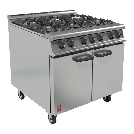
DOMINATOR
GAS RANGE APPLIANCES
(Refer to Section 1.1 for models covered by this document)
INSTALLATION and SERVICING
INSTRUCTIONS
This appliance must be installed and serviced by a competent person as stipulated by the Gas
Safety (Installation & Use) Regulations.
IMPORTANT
The installer must ensure that the installation of the appliance is in conformity with these instructions and
National Regulations in force at the time of installation. Particular attention MUST be paid to:
Gas Safety (Installation & Use) Regulations
Health And Safety At Work etc. Act
Local and National Building Regulations
Fire Precautions Act
These appliances have been UKCA/CE-marked based on compliance with the Gas Appliance Regulations/
Product Safety and Metrology Regulations for the Countries, Gas Types and Pressures as stated on the data
plate.
WARNING
TO PREVENT SHOCKS, ALL APPLIANCES WHETHER GAS OR ELECTRIC, MUST BE
: -
EARTHED.
On completion of the installation, these instructions should be left with the Engineer-in-Charge for
reference during servicing. Further to this, The Users Instructions should be handed over to the User,
having had a demonstration of the operation and cleaning of the appliance.
IT IS MOST IMPORTANT THAT THESE INSTRUCTIONS BE CONSULTED BEFORE INSTALLING
AND COMMISSIONING THIS APPLIANCE. FAILURE TO COMPLY WITH THE SPECIFIED
PROCEDURES MAY RESULT IN DAMAGE OR THE NEED FOR A SERVICE CALL.
PREVENTATIVE MAINTENANCE CONTRACT
To obtain maximum performance from this unit regular servicing of the appliance should be undertaken to
ensure correct operation, it is functioning as intended, and safe to use. We recommend servicing in
accordance with SFG20 Maintenance Schedules and as a minimum, after 2,500 hours of use, or annually,
whichever comes
first and
may then be made at agreed intervals to carry out adjustments and repairs.
WEEE Directive Registration No.
WEE/DC0059TT/PRO At end of unit life, dispose of
appliance and any replacement parts in a safe
manner, via a licensed waste handler.
Units are designed to be dismantled easily and recycling
of all material is encouraged whenever practicable.
Falcon Foodservice Equipment
HEAD OFFICE AND WORKS
Wallace View, Hillfoots Road, Stirling. FK9 5PY. Scotland.
SERVICELINE CONTACT
Phone: 01438 363 000
PLUS
that a maintenance contract be arranged with an appointed service contact. Visits
Fax: 01438 369 900
Detailed recommendations are contained in
Institute of Gas Engineers published documents:
IGE/UP1, IGE/UP/2
BS6173 and BS5440
T100753 Ref. 11
Advertisement
Table of Contents

Related Manuals for Falcon DOMINATOR PLUS G3101


Summary of Contents for Falcon DOMINATOR PLUS G3101
- Page 1 Units are designed to be dismantled easily and recycling of all material is encouraged whenever practicable. Falcon Foodservice Equipment HEAD OFFICE AND WORKS Wallace View, Hillfoots Road, Stirling. FK9 5PY. Scotland. T100753 Ref. 11...
- Page 2 IMPORTANT INFORMATION Warranty Policy Shortlist Warranty does not cover :- • Correcting faults caused by incorrect installation of a product. • Where an engineer cannot gain access to a site or a product. • Repeat commission visits. • Replacement of any parts where damage has been caused by misuse. •...
-
Page 3: Section 1 - Installation
SECTION 1 - INSTALLATION UNLESS OTHERWISE STATED, PARTS WHICH HAVE BEEN PROTECTED BY THE MANUFACTURER ARE NOT TO BE ADJUSTED BY THE INSTALLER. MODEL NUMBERS, NETT WEIGHTS and DIMENSIONS Width Depth Height Weight Model (mm) (mm) (mm) (kg) G3101 Six Burner Range G3101D Six Burner Range G3107 Solid Top Range G3107D Solid Top Range... -
Page 4: Gas Supply
GAS SUPPLY The incoming service must be of sufficient size to supply full rate without excessive pressure drop. A gas meter is connected to the service pipe by gas supplier. Any existing meter should be checked by supplier to ensure it is of adequate capacity to pass required rate for appliance in addition to any other gas equipment installed. - Page 5 INJECTOR DIAMETERS Model Natural Propane Butane I3+ and I3B/P Open Top Ø1.93mm Ø1.2mm Ø1.05mm 900mm Ø2.2 mm Ø 1.35mm Ø1.15mm 600mm Ø1.8mm Ø 1.09mm Ø1.0mm Solid Top Ø2.65mm Amal 360 Amal 360 1.8.1 Solid Top Pilot Injectors Natural Gas Propane Gas SIT No.
-
Page 6: Section 2 - Assembly And Commissioning
SECTION 2 - ASSEMBLY and COMMISSIONING ASSEMBLY Note The following paragraphs should be read as applicable to the unit being assembled. a) Unpack appliance and place it in position using feet adjusters to level appliance. b) Units with castors should be fitted with accessories supplied according to separate instructions provided. - Page 7 CONNECTION TO GAS SUPPLY Connect appliance to gas supply and ensure that the governor supplied is fitted on NATURAL gas installations. Test for gas tightness. The integral gas supply downstream of gas valve may be checked by applying leak detection spray with burner lit.
-
Page 8: Section 3 - Servicing And Conversion
SECTION 3 - SERVICING AND CONVERSION MAINTENANCE CHECK Regular servicing of the appliance should be undertaken to ensure correct operation, it is functioning as intended, and safe to use. We recommend servicing after 2,500 hours of use, or annually, whichever comes first. - Page 9 3.1.3 Oven Burner - To Replace Injector a) Remove oven shelves and base plate. b) Disconnect Gas supply pipe. c) Unscrew and remove existing injector. d) Insert and screw in replacement injector. e) Re-connect Gas supply pipe. 3.1.4 Thermostat - To Replace Bypass Screw (Figure 7) a) Remove control panel.
- Page 10 REMOVAL OF CONTROL PANELS Various panels are removed as follows: 3.2.1 To Remove Facia Panel Remove control knob(s). Open oven doors and undo fixings along underside and top. Pull facia panel forward while slightly easing bottom edge upward to remove. 3.2.2 To Remove Open Top Hob Components Remove pan supports and burner heads complete with aluminium bezels and venturi that sit...
- Page 11 THERMOCOUPLES and FLAME FAILURE DEVICE (FFD) 3.6.1 Open Top Flame Failure Device Magnet Unit To remove and replace FFD magnet unit, the following procedures must be followed. Isolate Gas supply. Remove hob components as detailed in Section 3.2.2. Undo FFD thermocouple at rear of tap, undo FFD section at tap rear and withdraw.
-
Page 12: Oven Thermostat
Thermostat Calibration The thermostat should not be calibrated. If temperature is outwith specified tolerances, replace thermostat and return faulty thermostat to Falcon Quality Department. OPEN TOP and SOLID TOP GAS TAPS Note - Plugs and bodies are machined in pairs and are therefore not interchangeable. -
Page 13: Section 4 - Spares And Accessories
9. If flame is still not present, then re-check from start. If flame is established but not maintained, follow this check list. 1. Check thermocouple is positioned correctly in burner flame. (fig 12) Burner ports must be clean. 2. Check thermocouple is not damaged and is secured to gas valve FFD section to allow FFD to energise.
Need help?
Do you have a question about the DOMINATOR PLUS G3101 and is the answer not in the manual?
Questions and answers