Table of Contents
Advertisement
Quick Links
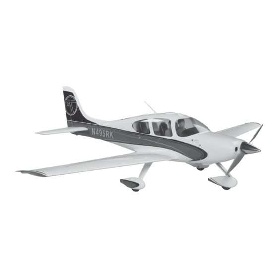
SPECIFICATIONS
Wingspan: 69 in [1753mm]
Length: 47-3/4 in [1213mm]
Weight: 7.5 – 8.25 lb [3400 – 3740 g]
2
Wing Area: 493 in
Wing Loading: 35 – 39 oz/ft
WARRANTY
Great Planes
®
Model Manufacturing Co. guarantees this kit to
be free from defects in both material and workmanship at the
date of purchase. This warranty does not cover any component
parts damaged by use or modification. In no case shall Great
Planes' liability exceed the original cost of the purchased kit.
Further, Great Planes reserves the right to change or modify this
warranty without notice.
In that Great Planes has no control over the final assembly or
material used for final assembly, no liability shall be assumed nor
accepted for any damage resulting from the use by the user of
the final user-assembled product. By the act of using the
user-assembled product, the user accepts all resulting liability.
If the buyer is not prepared to accept the liability associated
with the use of this product, the buyer is advised to return
READ THROUGH THIS MANUAL BEFORE STARTING CONSTRUCTION. IT CONTAINS IMPORTANT
INSTRUCTIONS AND WARNINGS CONCERNING THE ASSEMBLY AND USE OF THIS MODEL.
®
Entire Contents © 2013 Hobbico,
Inc. All rights reserved.
2
[31.8 dm
]
2
2
[107– 119 g /dm
]
INSTRUCTION MANUAL
Engine: .46–.55 [7.5 – 8.9cc] two-stroke glow engine or
.70–.72 [11.5– 11.8cc] four-stroke glow engine
Electric: RimFire .55, O.S. 50 Motor
Radio: 6-channel
this kit immediately in new and unused condition to the
place of purchase.
To make a warranty claim send the defective part or item to
Hobby Services at the address below:
3002 N. Apollo Dr. Suite 1
Champaign IL 61822 USA
Include a letter stating your name, return shipping address, as
much contact information as possible (daytime telephone
number, fax number, e-mail address), a detailed description of
the problem and a photocopy of the purchase receipt. Upon
receipt of the package the problem will be evaluated as quickly
as possible.
.55-.72 GP
55 EP
Hobby Services
Champaign, Illinois
(217) 398-8970, Ext 5
airsupport@greatplanes.com
GPMA1363 Mnl
Advertisement
Table of Contents

Subscribe to Our Youtube Channel
Related Manuals for GREAT PLANES SR22 Turbo


Summary of Contents for GREAT PLANES SR22 Turbo
-
Page 1: Instruction Manual
3002 N. Apollo Dr. Suite 1 Champaign IL 61822 USA In that Great Planes has no control over the final assembly or material used for final assembly, no liability shall be assumed nor Include a letter stating your name, return shipping address, as... -
Page 2: Table Of Contents
For the latest technical updates or manual corrections to the Or via the Internet at: http://www.modelaircraft.org “Cirrus SR22 ARF” visit the Great Planes web site at www. greatplanes.com. Open the “Airplanes” link, then select the IMPORTANT!!! Two of the most important things you can “Cirrus SR22 ARF”. -
Page 3: Safety Precautions
A LiPo compatible charger is required to charge the LiPo you build it; therefore, we cannot in any way guarantee the battery. The Great Planes ElectriFly Triton2 EQ AC/DC performance of your completed model, and no representa- Charger is designed for LiPo packs, but is also capable of tions are expressed or implied as to the performance or charging NiCd, NiMH, Pb acid and LiFe batteries. -
Page 4: Radio Equipment
❍ Stick-on segmented lead weights (GPMQ4485) Radio Equipment ❍ 36" Metal Ruler (HCAR0475) ❍ Pliers with wire cutter (HCAR0625) The Cirrus SR22 ARF requires a 5-channel (6-channel if using ❍ Dremel the optional lights) radio system with three standard servos with ®... -
Page 5: Kit Inspection
Fuselage ORDERING REPLACEMENT PARTS GPMA3411 Wing Set GPMA3412 Tail Surface Set Replacement parts for the Great Planes Cirrus SR22 are GPMA3413 Cowl available using the order numbers in the Replacement Parts GPMA3414 Hatch/Canopy List that follows. The fastest, most economical service can... -
Page 6: Preparations
PREPARATIONS ❏ 1. If you have not done so already, remove the major parts of the kit from the box and inspect for damage. If any parts are damaged or missing, contact Product Support at the address or telephone number listed in the “Kit Inspection” section. ❏... - Page 7 ❏ ❏ ❏ ❏ 6. Use the string in the wing to pull the aileron servo 10. Position the control horn so that it is inline with wire through the wing. the aileron servo horn and the clevis pin is aligned with the aileron hinge line.
-
Page 8: Install The Flap Servo
Use the servo cover as a guide to drill 1/16" [1.6mm] holes Install the Flap Servo through the plate in the wing. Secure the cover using four #2 ❏ ❏ x 3/8" [9.5mm] sheet metal screws and four #2 fl at washers. 1. -
Page 9: Install The Main Landing Gear
Install the Main Landing Gear ❏ ❏ 4. Apply a drop of thread locker to the threads of a 6-32 x 1/4" [6mm] socket head cap screw. Slide a 4mm wheel collar onto the axle. Thread the 6-32 x 1/4" [6mm] socket head cap screw into the wheel collar and tighten it on ❏... -
Page 10: Assemble The Fuselage
ASSEMBLE THE FUSELAGE Install the Stabilizer ❏ 4. Use epoxy to glue the two 1/8" x 5/8" [3 x 16mm] nylon stabilizer dowels 5/16" [8mm] into the root of the stabilizers. ❏ 1. Insert the carbon fi ber wing joiner tube in the fuselage. Slide the two wing halves onto the tube and secure the wing halves to the fuselage with two 1/4-20 nylon wing bolts. -
Page 11: Install The Elevator And Rudder Servo
❏ the way into the elevator halves. Use a toothpick to remove 8. Gather together a couple of sheets of paper towel, any excess epoxy the squeezes out. Then, fi t the elevator denatured alcohol, mixing cup, mixing stick, epoxy brush, 8" halves the rest of the way on. -
Page 12: Install The Nose Gear
Install the Nose Gear ❏ 4. Position the control horn on the elevator so that the four holes on the control horn are inline with the elevator hinge line. Mark the two control horn mounting holes on the elevator. Remove the control horn and drill a 1/16" [1.6mm] pilot hole at each mark. - Page 13 ❏ 3. Use sandpaper to roughen the nose gear wire (where ❏ shown) and the slot in the wheel pant. Then clean both 6. Install the nose gear axle assembly on the nose gear areas with a paper towel dampened with denatured alcohol. wire.
- Page 14 ❏ 9. Install the nylon nose gear steering block to the front of the fuselage with four 6-32 x 5/8" [16mm] socket head cap screws, #6 fl at washers and #6 lock washers. Apply a drop of thread locker on the threads of the cap screws before installing.
-
Page 15: Install The Motor
Install the Motor Note: If you are installing a glow engine, proceed to page 17, Install The Engine. ❏ 14. Make a bend in the steering pushrod so that it is aligned with the screw-lock pushrod connector. Center the servo arm and nose wheel. Cut the steering pushrod 1/4"... - Page 16 ❏ 4. Attach the motor box to the fi rewall with four 6-32 x 5/8" [16mm] socket head cap screws, #6 fl at washers and #6 lock washers. Be sure to apply a drop of thread locker to the threads of the cap screws. ❏...
-
Page 17: Install The Engine
❏ 7. Make a hole in the front of the fuselage to route the Install the Engine battery plug and ESC control wire into the fuselage. Plug the ESC into the receiver. Connect the three motor wires to the ESC. See page 21, step 5 for hole location. ❏... - Page 18 ❏ 7. Make the throttle pushrod by threading a nylon clevis 20 turns onto the leftover 2-56 x 17-1/2" [444mm] metal pushrod (previously cut from the 36" [914mm] metal pushrod). Slide a silicone clevis retainer over the clevis. ❏ 3. Install the engine on the engine mount with four 6-32 x 1"...
-
Page 19: Install The Fuel Tank
connector with a nylon retainer. Switch on the radio system. Install the Fuel Tank Center the throttle stick on the transmitter and install a servo arm on the throttle servo perpendicular to the centerline of the servo. ❏ 1. Insert the one long and two short aluminum tubes through the large fuel tank stopper plate, rubber fuel tank stopper and the small fuel tank stopper plate. -
Page 20: Install The Cowl
❏ 4. Place the plywood fuel tank spacer over the neck of the fuel tank. ❏ 7. Install the muffl er and connect the fuel line from the pressure tube to the muffl er. The end of the muffl er screw may need to be fi... - Page 21 ❏ ❏ 2. Remove the muffl er. Install the cabin/hatch on the 5. On the left front side of the fuselage, cut a hole to route fuselage. Slide the cowl over the engine or motor. Trim the the landing light wires into the fuselage. bottom of the cowl to fi...
- Page 22 Remove the cowl and enlarge the holes in the cowl with a 3/32" [2.4mm] drill bit. We use a Top Flite Precision Magnetic Prop Balancer (TOPQ5700) in the workshop and keep a Great Planes Fingertip Prop Balancer (GPMQ5000) in our fl ight box. ❏...
-
Page 23: Install The Receiver Battery
Install the Receiver Battery ❏ 4. If the plane is nose heavy, wrap the receiver battery in R/C foam and secure it between the servos with a hook and loop strap. If the plane is tail heavy, the receiver battery can ❏... -
Page 24: Apply The Decals
❏ ❏ 3. Now is a good time to organize the wires in the fuselage. 6. Glue the cabin bottom cover in place. Connect the aileron and fl ap servos to the Y-harnesses. Straps to hold the wires in position can be made from #64 rubber bands (not included) cut into strips. -
Page 25: Get The Model Ready To Fly
Please use the following pictures and box top as a guide for GET THE MODEL READY TO FLY the decal placement. Balance the Model Laterally ❏ 1. With the wing level, have an assistant help you lift the model by the propeller shaft and the bottom of the fuse under the TE of the fi... -
Page 26: Set The Control Throws
Set the Control Throws At the Servos To ensure a successful fi rst fl ight, set up your Cirrus SR22 The pushrod farther out The pushrod closer in ARF according to the control throws specifi ed in this means More Throw means Less Throw manual. -
Page 27: Balance The Model (C.g.)
Instead, permanently attach the weight with ❏ 1. If using a Great Planes C.G. Machine, set the rulers to glue or screws. 2-1/4" [57mm]. If not using a C.G. Machine, use a fi ne-point... -
Page 28: Ground Check And Range Check
The engine and motor get hot! Do not touch during or right CAUTION: Unless the instructions that came with your after operation. Make sure fuel lines are in good condition so radio system state differently, the initial charge on new fuel will not leak onto a hot engine, causing a fi... -
Page 29: Check List
❏ 4) I will operate my model using only radio control frequencies 14. Make sure the fuel lines are connected and are not currently allowed by the Federal Communications Commission. kinked. ❏ 5) I will not knowingly operate my model within three 15. -
Page 30: Takeoff
to overshoot, smoothly advance the throttle (always ready Takeoff on the right rudder to counteract torque) and retract the fl aps when enough airspeed is gained. Climb out to make Before you get ready to takeoff, see how the model handles another attempt.
Need help?
Do you have a question about the SR22 Turbo and is the answer not in the manual?
Questions and answers