Table of Contents
Advertisement
Quick Links
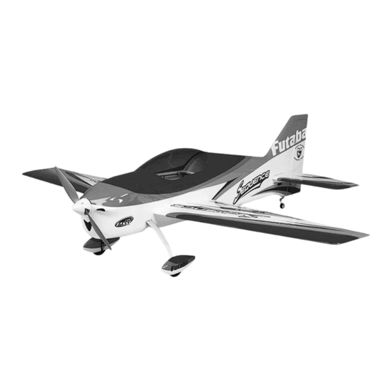
Wingspan:
50 in
[1270mm]
Wing Area:
505 sq in
[32.6 dm
WARRANTY
Great Planes
®
Model Manufacturing Co. guarantees this kit to
be free from defects in both material and workmanship at the
date of purchase. This warranty does not cover any component
parts damaged by use or modification. In no case shall Great
Planes' liability exceed the original cost of the purchased kit.
Further, Great Planes reserves the right to change or modify this
warranty without notice.
In that Great Planes has no control over the final assembly or
material used for final assembly, no liability shall be assumed nor
accepted for any damage resulting from the use by the user of
the final user-assembled product. By the act of using the
user-assembled product, the user accepts all resulting liability.
If the buyer is not prepared to accept the liability associated
with the use of this product, the buyer is advised to return
READ THROUGH THIS MANUAL BEFORE STARTING CONSTRUCTION. IT CONTAINS IMPORTANT
INSTRUCTIONS AND WARNINGS CONCERNING THE ASSEMBLY AND USE OF THIS MODEL.
Entire Contents © Copyright 2009
Weight:
3.5– 3.75 lb
[1590-1700 g]
Wing
16– 17 oz/sq ft
2
]
Loading:
[49– 52 g/dm
MF
WA
SPECIFICATIONS
Length:
51.5 in
[1310mm]
Motor:
RimFire .32 (42-50-800)
brushless out-runner motor
2
]
this kit immediately in new and unused condition to the
place of purchase.
To make a warranty claim send the defective part or item to
Hobby Services at the address below:
3002 N. Apollo Dr. Suite 1
Champaign IL 61822 USA
Include a letter stating your name, return shipping address, as
much contact information as possible (daytime telephone
number, fax number, e-mail address), a detailed description of
the problem and a photocopy of the purchase receipt. Upon
receipt of the package the problem will be evaluated as quickly
as possible.
GR
RADIO
4-channel
w/4 micro servos
and standard
size receiver
Hobby Services
Champaign, Illinois
(217) 398-8970, Ext 5
airsupport@greatplanes.com
minimum
GPMA1575 Mnl
Advertisement
Table of Contents

Related Manuals for GREAT PLANES Sequence


Summary of Contents for GREAT PLANES Sequence
- Page 1 3002 N. Apollo Dr. Suite 1 Champaign IL 61822 USA In that Great Planes has no control over the final assembly or material used for final assembly, no liability shall be assumed nor Include a letter stating your name, return shipping address, as...
-
Page 2: Table Of Contents
IMPORTANT BUILDING NOTES ....5 the Sequence ARF visit the Great Planes web site at www. COMMON ABBREVIATIONS ..... . .5 greatplanes.com. -
Page 3: Safety Precautions
2. You must assemble the model according to the instructions. Do not alter or modify the model, as doing This is a partial list of items required to fi nish the Sequence so may result in an unsafe or unfl yable model. In a few ARF that may require planning or decision making cases the instructions may differ slightly from the photos. -
Page 4: Propeller
Top Flite MonoKote trim seal iron (TOPR2200) This is the list of hardware and accessories required to ❏ Top Flite MonoKote heat gun (TOPR2000) fi nish the Sequence ARF. Order numbers are provided in ❏ Hobbico Pin Vise 1/16 Collet w/6 Bits (HCAR0696) parentheses: ❏... -
Page 5: Building Stand
3002 N Apollo Drive, Suite 1 Fax: (217) 398-7721 to get another view of the same parts. Champaign, IL 61822 • The Sequence is factory-covered with Top Flite MonoKote E-mail: airsupport@greatplanes.com fi lm. Should repairs ever be required, MonoKote can be... -
Page 6: Kit Contents
ORDERING REPLACEMENT PARTS Product Support by e-mail at productsupport@greatplanes. com, or by telephone at (217) 398-8970. Replacement parts for the Great Planes Sequence ARF are available using the order numbers in the Replacement Parts REPLACEMENT PARTS LIST List that follows. The fastest, most economical service can be provided by your hobby dealer or mail-order company. -
Page 7: Building Instructions
BUILDING INSTRUCTIONS Preparations ❏ 1. If you have not done so already, remove the major parts of the kit from the box and inspect for damage. If any parts are damaged or missing, contact Product Support at the address or telephone number listed in the “Kit Inspection” section on page 5. - Page 8 CORRECT INCORRECT Enlarge to 5/64" [2mm] Cut off unused arms Hinge Line Hinge Line ❏ 4. Cut three arms from a four-armed servo arm for each aileron servo. Enlarge the outer hole of the remaining arm with a 5/64" [2mm] drill bit. Center the servos with your radio ❏...
-
Page 9: Install The Horizontal
INSTALL THE HORIZONTAL STABILIZER AND ELEVATORS Pushrod Wire Servo Horn FasLink Pushrod Connector ❏ 1. Insert the carbon wing joiner into the outer wing tube in the fuselage and center it left and right. Slide the wing panels onto the tube and tighten them down using the included wing bolts. - Page 10 Cut the covering away from the slot. ❏ 4. Drill a 3/32" [2.4mm] hole 1/2" [13mm] deep into the center of each hinge slot in the elevator halves and stab. Trim the covering away from each hinge slot to ensure that the hinges will be properly glued in place.
-
Page 11: Install The Landing Gear
joiner wire with sandpaper and clean them with denatured alcohol. Mix up a small amount of epoxy and coat the ends of the joiner wire. Install the elevator halves onto the stab with CA hinges, being sure that there are even gaps between the stab tips and elevators on each side. -
Page 12: Install The Tail Servos & Pushrods
❏ 9. Reinstall the spacers, wheel collars and wheels onto the axles. Thread a 6-32 set screw into each wheel collar and tighten the screws against the fl at spots on the axles. Be sure that the wheel rotates freely on the axle. Oil the axles if necessary. - Page 13 ❏ 1. Install the elevator servo on the far right side of the tail servo mounting rails using the screws that come in the servo hardware bag and two fi berglass plates. Be sure to reinforce the screw holes in the rails with thin CA. ❏...
- Page 14 the end of it. Insert the pushrod into the elevator exit slot and attach the clevis to the outer hole of the elevator control horn. With the elevators in the neutral position and the elevator servo centered, mark the pushrod where it crosses the middle hole of the elevator servo arm.
- Page 15 may want to mark the location of the hole on each side of the rudder and partly drill through the rudder from each side, then connect the two holes by drilling through the entire thickness of the rudder. Apply a few drops of thin CA to the hole to harden the surrounding wood.
-
Page 16: Aft Tail Servo Installation
Aft Tail Servo Installation A 24" [610mm] servo extension will be needed for the rudder and elevator servos. Installation is the same as the aileron pushrods. Use the photos and text below as a general guide for the location of the servos and control horns. Refer back to the aileron pushrod installation for pushrod details. - Page 17 ❏ 4. Cut strips of self-adhesive from the hook side of a package of self-adhesive hook and loop material (not included) and apply them down the length of the battery tray as shown. The loop side should be applied to the underside of your battery pack.
-
Page 18: Finish The Model
FINISH THE MODEL ❏ 3. If you have installed the recommended motor, you will need to drill or ream the propeller and spinner backplate to 5/16" [7.9mm]. Install the spinner backplate onto the prop adapter followed by the prop, prop washer, and prop nut. ❏... -
Page 19: Get The Model Ready To Fly
GET THE MODEL READY TO FLY Install and Operate the Motor Battery (Brushless Only) NO!!! IMPORTANT: If using multiple battery packs that are connected with an adapter, never charge the batteries together through the adapter. Always charge each battery pack separately. NEVER connect battery packs with different Voltages in Charge the batteries, then read the following precautions on Parallel–only combine in Series. -
Page 20: Set The Control Throws
Adjust if necessary. with the greatest chance for successful fi rst fl ights. If, after you have become accustomed to the way the Sequence Set the Control Throws fl ies, you would like to change the throws to suit your taste, that is fi... -
Page 21: Balance The Model Laterally
Charge the Batteries of the model installed (ready to fl y), place the model upside- down on a Great Planes CG Machine, or lift it upside-down Follow the battery charging instructions that came with at the balance point you marked. -
Page 22: Range Check
ONLY charge through the “charge” lead. NEVER We use a Top Flite Precision Magnetic Prop Balancer charge through the “discharge” lead. (TOPQ5700) in the workshop and keep a Great Planes • Fingertip Prop Balancer (GPMQ5000) in our fl ight box. -
Page 23: Check List
FLYING model other than the landing gear, intentionally touch the ground, except while landing. The Sequence ARF is a great-fl ying model that fl ies smoothly and predictably. The Sequence does not, however, possess CHECK LIST the self-recovery characteristics of a primary R/C trainer and should be fl... -
Page 24: Flight
GOOD LUCK AND GREAT FLYING! takeoff, most models fl y more smoothly at reduced speeds. Take it easy with the Sequence for the fi rst few fl ights, gradually getting acquainted with it as you gain confi dence. Adjust the trims to maintain straight and level fl ight. After fl ying around for a while and while still at a safe altitude with plenty of battery charge, practice slow fl...
Need help?
Do you have a question about the Sequence and is the answer not in the manual?
Questions and answers