Table of Contents
Advertisement
Quick Links
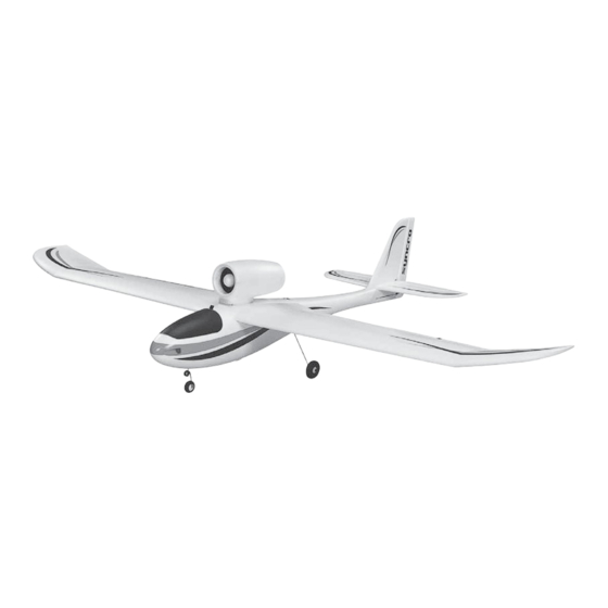
SPECIFICATIONS
Wingspan: 55.5 in
[1410mm]
Wing Area: 400 in
[25.8 dm
Weight: 28 – 29.5 oz
[795 – 835 g]
Wing
10.1 – 10.6 oz/ft
Loading:
[31 – 32 g /dm
WARRANTY
Great Planes
Model Manufacturing Co. guarantees this kit to
®
be free from defects in both material and workmanship at the
date of purchase. This warranty does not cover any component
parts damaged by use or modification. In no case shall Great
Planes' liability exceed the original cost of the purchased kit.
Further, Great Planes reserves the right to change or modify this
warranty without notice.
In that Great Planes has no control over the final assembly or
material used for final assembly, no liability shall be assumed nor
accepted for any damage resulting from the use by the user of
the final user-assembled product. By the act of using the
user-assembled product, the user accepts all resulting liability.
If the buyer is not prepared to accept the liability associated
with the use of this product, the buyer is advised to return
READ THROUGH THIS MANUAL BEFORE STARTING CONSTRUCTION. IT CONTAINS IMPORTANT
INSTRUCTIONS AND WARNINGS CONCERNING THE ASSEMBLY AND USE OF THIS MODEL.
®
© 2011 Hobbico
, Inc.
Wingspan: 31.5 in
Wing Area: 219 in
2
2
]
Weight: 22.5 – 24.0 oz
2
Wing
2
]
Loading:
INSTRUCTION
[800mm]
2
Length:
2
[14.1 dm
]
Radio:
[640 – 680 g]
14.8 – 15.8 oz/ft
2
Motor, ESC,
Battery
[45 – 48 g /dm
2
]
this kit immediately in new and unused condition to the
place of purchase.
To make a warranty claim send the defective part or item to
Hobby Services at the address below:
3002 N. Apollo Dr. Suite 1
Champaign IL 61822 USA
Include a letter stating your name, return shipping address, as
much contact information as possible (daytime telephone
number, fax number, e-mail address), a detailed description of
the problem and a photocopy of the purchase receipt. Upon
receipt of the package the problem will be evaluated as quickly
as possible.
airsupport@greatplanes.com
™
MANUAL
34.5 in
[875mm]
4-Channel with 6 micro servos
and standard receiver
24-33-4040 Ammo
11.1V 1800 – 2200mAh LiPo
Hobby Services
Champaign, Illinois
(217) 398-8970, Ext 5
™
, 25A ESC
GPMA1581 Mnl
Advertisement
Table of Contents

Subscribe to Our Youtube Channel
Related Manuals for GREAT PLANES SYNCRO


Summary of Contents for GREAT PLANES SYNCRO
- Page 1 3002 N. Apollo Dr. Suite 1 Champaign IL 61822 USA In that Great Planes has no control over the final assembly or material used for final assembly, no liability shall be assumed nor Include a letter stating your name, return shipping address, as...
-
Page 2: Table Of Contents
Syncro, if not assembled and operated correctly, could FLYING THE SYNCRO ......19 possibly cause injury to yourself or spectators and damage Find a Suitable Flying Site . -
Page 3: Additional Items Required
21 Amps on the ground (static) at full-throttle. Although this is slightly over the constant current limit (of 18 Amps), it will drop to or below this limit when the plane is in the air, so the Syncro may be flown full-throttle for as... -
Page 4: Ordering Replacement Parts
To locate a hobby dealer, visit the Great Planes web site simultaneously (reducing down time and optimizing flight at greatplanes.com. Choose “Where to Buy” at the ™ time), the Great Planes PolyCharge4 DC-powered LiPo bottom of the menu on the left side of the page. -
Page 5: Kit Inspection
If any parts are missing or are not of acceptable quality, or if you need assistance with assembly, contact Product Support. When reporting defective or missing parts, use the part names exactly as they are written in the Kit Contents list. Great Planes Product Support: 3002 N Apollo Drive, Suite 1 Champaign, IL 61822 Telephone: (217) 398-8970, ext. -
Page 6: Assemble The Wings
ASSEMBLE THE WINGS Cut off the unused arms After the spar covers are permanently glued into place, the ends of the Y-connector for the aileron servos will no longer be accessible. The servos may still be removed by pulling the wires out of the wing, but the wing will no longer be functional because it will not be possible to re-connect new servos. -
Page 7: Hook Up The Ailerons
Hook up the Ailerons SERVO CONTROL SURFACE ❏ 1. If working on the glider wing (pictured), connect one of the shorter Z-bend pushrods to the outer hole of the servo arm on the servo in the right wing panel. Insert a screw-lock connector into the bottom hole in the aileron control horn Moving the pushrod outward and fi... -
Page 8: Finish The Wing
❏ 6. Still with the radio on, remove the screw in the screw- lock connector, wet the threads with threadlocker, reinstall the screw and tighten it securely making sure the aileron remains centered. ❏ 7. Connect the other pushrod to the other aileron and servo the same way. - Page 9 SPORT WING: ❏ 6. Test-fi t, but do not glue in the spar covers. Once you see that the spar and spar covers fi t well, remove and apply glue all ❏ 1. Connect the short Y-connector to the aileron servo wires. the way around the spar—an epoxy brush is great for spreading Use a drop of glue to hold the connectors in the channel so the glue.
-
Page 10: Mark The C.g. (Balance Point)
SPORT WING: Mark the C.G. (Balance Point) GLIDER WING: 4" [102mm] 4" [102mm] Balance Lines 4" [102mm] 4" [102mm] 2-3/4" [70mm] 2-3/4" [70mm] Balance Lines 2-1/2" [64mm] 2-1/2" [64mm] 3-1/8" [79mm] 3-1/8" [79mm] 2-3/8" [60mm] 2-3/8" [60mm] 2-3/4" [70mm] 2-3/4" [70mm] 2-1/4"... -
Page 11: Assemble The Fuselage
ASSEMBLE THE FUSELAGE Install the Landing Gear (Optional) The landing gear for the Syncro is optional. If you prefer the streamlined appearance of a glider (with the glider wing) or the jet-like appearance with the landing gear retracted (with the sport wing) you may simply leave the landing gear off. -
Page 12: Install The Servos
❏ 8. Remove the wing. Test-fi t, then glue the pinned hinge into the bottom of the rudder and the fuselage—use care not to get any glue into the hinge pin. As a precaution, you could add a dab of petroleum jelly or plastic-compatible oil to the hinge joint. -
Page 13: Assemble The Ducted Fan
Assemble the Ducted Fan ❏ 1. Remove the female “bullet” connectors from the ducted fan motor (not included). These will not be used because ❏ 2. Fit the pushrods into the middle hole in the elevator the recommended SS-25 ESC already has connectors on control horn and into the lowest hole—the one closest to the the wires. - Page 14 ❏ 4. Use a hobby knife to enlarge the hole in the fan housing to accommodate the adapter shaft on the motor. ❏ 6. Fit the fan onto the adapter shaft keying the notches in the back of the fan over the set screws protruding from the shaft.
-
Page 15: Test Run The Motor
it into position with four to six drops of medium CA. Note that, Test Run the Motor if ever the motor requires removal, the tail cone will have to be broken free from the fan housing. This should not prove to Before mounting the fan cone and proceeding with the rest be diffi... - Page 16 ❏ 10. Once you can get the motor and fan to run smoothly CAUTION: In the next step we will be running the fan at 1/3-throttle for one full minute, advance the throttle to 2/3 to full power, so proceed with great care and wear stick and run for another minute, then fi...
-
Page 17: Final Preparations
FINAL PREPARATIONS Mount the Receiver and ESC ❏ 4. Place the wing on the fuselage making sure none of the wires are pinched between the bottom of the wing and the fuselage. Bolt the wing to the fuselage with the 35mm Phillips sheet metal screw and the 3mm washer—do not over-tighten the screw—just about 1 to 1-1/2 turns after the ❏... -
Page 18: Check The Control Throws
fl own, but it’s really best to get the model to balance directly on the middle lines as recommended. This is where the Syncro will fl y best. Balance the model as instructed in the following steps. -
Page 19: Identify Your Model
Pilots with little experience should initially fl y their Syncro with a smaller battery it is likely that nose weight will be required the glider wing. The glider wing will enable the Syncro to fl y and this is not at all unusual. Determine how much weight slowly and be more “forgiving.”... -
Page 20: Set A Flight Timer
“up” elevator to start climbing and use the ailerons to keep the wings level. Take Off Until you are confi dent fl ying your Syncro, do not fl y if the wind speed is greater than 10 mph [16 kph]. One fi nal check before takeoff; check the control response to your transmitter inputs—this should be done before... -
Page 21: Rog (Rise Off Ground)
Continue to fl y your Syncro, getting used to how it responds before fi nally coming in to land. - Page 22 NOTES...
- Page 23 Bearings are double-shielded and there are no brushes to burn out. Installed, gold-plated bullet connectors are compatible with brushless ElectriFly ESCs. (GPMG5165) ElectriFly ™ ElectriFly by Great Planes Silver Series SS-25 Brushless Electronic Speed Control Input Voltage: 7.2-14.8V Max. Continuous Current: 25A BEC: 5V/2.0A Dimensions: 1.58 x 0.31 x 1.02 in (40 x 8 x 26 mm)
Need help?
Do you have a question about the SYNCRO and is the answer not in the manual?
Questions and answers