AERMEC FCLI 32 Technical Manual
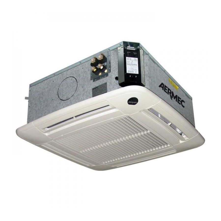
Cassette-type fan coil with inverter
Hide thumbs
Also See for FCLI 32:
- Installation manual (76 pages) ,
- Use and installation manual (59 pages) ,
- Technical manual (43 pages)
Table of Contents
Advertisement
Advertisement
Table of Contents


Need help?
Do you have a question about the FCLI 32 and is the answer not in the manual?
Questions and answers