AERMEC FCL 32 Technical Manual
Cassette-type fan coil
Hide thumbs
Also See for FCL 32:
- Installation manual (89 pages) ,
- Technical manual (76 pages) ,
- Service – technical manual (64 pages)
Table of Contents
Advertisement
CASSETTE-TYPE FAN COIL
FCL
FCL 32
(600x600)
FCL 36
(600x600)
FCL 42
(600x600)
FCL 62
(600x600)
FCL 72
(600x600)
FCL 34
(600x600)
FCL 38
(600x600)
FCL 44
(600x600)
FCL 64
(600x600)
T E C H N I C A L
FCL 82
(840x840)
FCL 102
(840x840)
FCL 122
(840x840)
FCL 84
(840x840)
FCL 104
(840x840)
FCL 124
(840x840)
IFCLTY 1112 - 4528511_04
Replace 1012 - 4528511_03
M A N U A L
Advertisement
Table of Contents

Related Manuals for AERMEC FCL 32


Summary of Contents for AERMEC FCL 32
- Page 1 T E C H N I C A L M A N U A L CASSETTE-TYPE FAN COIL FCL 32 FCL 82 (600x600) (840x840) FCL 36 FCL 102 (600x600) (840x840) FCL 42 FCL 122 (600x600) (840x840) FCL 62 FCL 84...
-
Page 2: Declaration Of Conformity
Carefully and thoroughly read all the information referred to AERMEC S.p.A. declines all liability for any damage due to in this manual. Pay particular attention to the instructions for improper use of the machine, or the partial or superficial read- use accompanied by the words “DANGER”... - Page 3 FCL + ZUBEHÖR sont pas fournis de Aermec. Falls das Gerät mit Zubehörteilen ausgerüstet wird, die nicht von Aermec geliefert werden, ist dessen Inbetriebnahme solange untersagt DECLARACIÓN DE CONFORMIDAD Los que suscriben la presente declaran bajo la propia y exclusiva responsabilidad que el conjunto en objeto, defi...
- Page 4 TRASPORTO • CARRIAGE • TRANSPORT • TRANSPORT • TRANSPORTE NON bagnare. Tenere al riparo NON calpestare dalla pioggia Do NOT step Do NOT wet NE PAS marcher sur cet emballage CRAINT l’humidité Nicht betreten Vor Nässe schützen NO pisar NO mojar Sovrapponibilità: controllare sull’imballo per conoscere il numero di macchine FCL (840x840) FCL (600x600)
- Page 5 IMPORTANT INFORMATION AND MAINTENANCE WARNING: the fan coil is connected DO NOT USE EXCESSIVELY HOT unpleasant smells due to the accumula- to the power supply and a water cir- WATER tion of substances present in the air of cuit. Any operation by persons who Clean the fan coil with a soft cloth or the room (clean the filter more often, do not possess the required technical...
- Page 6 The Cassette fan coils of the FCL range are available in two basic sizes, called "Modules" For 2-pipe systems For 4-pipe systems 7 sizes 7 sizes FCL 32 FCL 34 (Module 600) (Module 600) FCL 36 FCL 38 (Module 600)
- Page 7 Description of the functions of fan coils fi tted with GLL-M and GLL-R grille units - Cooling operation: the remote control dehumidifi cation mode. It is possible - Dehumidification operation: requires can be used to set the cooling mode to correct the fixed operation setting the circulation of cold water in the and the room temperature required by ±5°C, using the remote control.
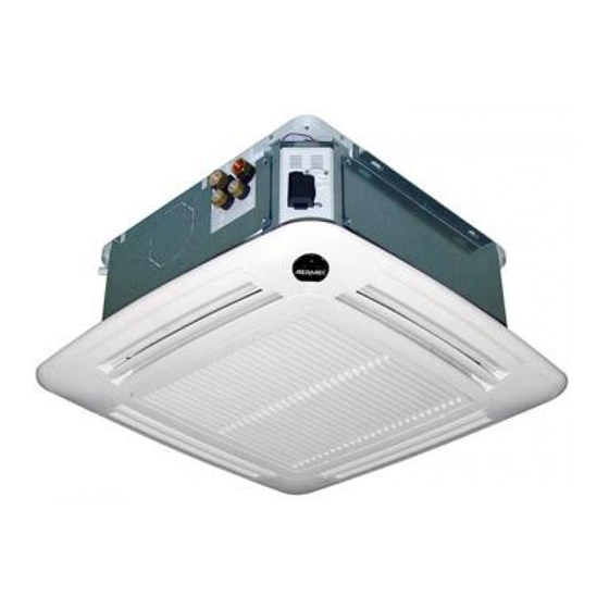
- Page 8 MAIN COMPONENTS 1 Grille with air filter 6 Base unit 11 Air drain valve 2 Receiver (GLL_M; GLL_R) 7 Fastening brackets 12 Push-out, coupling for air delivery in 3 Air delivery deflector 8 Electrical box an adjacent room 4 Grille frame 9 Water connections (only for 4 pipes) 13 Condensate drain 5 Tray...
- Page 9 The electric motor offers 3 speeds for ily removed for cleaning. smaller sizes (FCL 32-34-36-38) and The same standard FCL unit can be con- 4 speeds for larger sizes (to be able fi...
-
Page 10: Operating Limits
SELECTION CRITERIA The main technical data of the FCL The heating capacity in relation to description of each accessory, plus a range are summarised in the tables. the water flow rate, and to the drawing and its compatibility. temperature difference between the The tables show the sensible and total The installation information is included incoming water and the incoming... - Page 11 SYSTEM EXAMPLES Key: Ambient probe; Water probe RXLE Heater Solenoid valve (Hot/Cold), VHL1/2/20/22 Hot valve FCL (Standard) FCL (V2) 2-pipe system 4-pipe system 2-pipe system 4-pipe system VHL1 VHL2 VHL20 VHL22 FCL (Standard) FCL (V2) with electric heater with electric heater 2-pipe system 4-pipe system 2-pipe system...
-
Page 12: Technical Data
TECHNICAL DATA FCL 2-pipe versions Heating Speed 4 4950 6250 6750 7100 10600 13000 Speed 3 2380 3750 3940 4780 5230 5700 8300 10500 Heating capacity 50°C Speed 2 1760 2690 3030 3830 4490 4850 7000 8800 Speed 1 1330 2050 2250 3050... - Page 13 TECHNICAL DATA FCL 4-pipe versions Heating Speed 4 3070 3800 8500 10000 12500 Speed 3 2600 2600 2730 3380 7150 8250 10400 Heating capacity 70°C Speed 2 2190 2190 2290 2990 6400 7300 9300 Speed 1 1950 1950 1960 2640 5300 5900 7050...
- Page 14 COOLING CAPACITY - FCL32 Pc [W] Ps [W] Pc [W] Ps [W] Pc [W] Ps [W] Pc [W] Ps [W] Pc [W] Ps [W] Pc [W] Ps [W] T [°C] W.B. [°C] 21°C Ta D.B. 23°C Ta D.B. 25°C Ta D.B. 27°C Ta D.B.
- Page 15 COOLING CAPACITY - FCL32 Pc [W] Ps [W] Pc [W] Ps [W] Pc [W] Ps [W] Pc [W] Ps [W] Pc [W] Ps [W] Pc [W] Ps [W] T [°C] W.B. [°C] 21°C Ta D.B. 23°C Ta D.B. 25°C Ta D.B. 27°C Ta D.B.
- Page 16 COOLING CAPACITY - FCL36 Pc [W] Ps [W] Pc [W] Ps [W] Pc [W] Ps [W] Pc [W] Ps [W] Pc [W] Ps [W] Pc [W] Ps [W] T [°C] W.B. [°C] 21°C Ta D.B. 23°C Ta D.B. 25°C Ta D.B. 27°C Ta D.B.
- Page 17 COOLING CAPACITY - FCL36 Pc [W] Ps [W] Pc [W] Ps [W] Pc [W] Ps [W] Pc [W] Ps [W] Pc [W] Ps [W] Pc [W] Ps [W] T [°C] W.B. [°C] 21°C Ta D.B. 23°C Ta D.B. 25°C Ta D.B. 27°C Ta D.B.
- Page 18 COOLING CAPACITY - FCL42 Pc [W] Ps [W] Pc [W] Ps [W] Pc [W] Ps [W] Pc [W] Ps [W] Pc [W] Ps [W] Pc [W] Ps [W] T [°C] W.B. [°C] 21°C Ta D.B. 23°C Ta D.B. 25°C Ta D.B. 27°C Ta D.B.
- Page 19 COOLING CAPACITY - FCL42 Pc [W] Ps [W] Pc [W] Ps [W] Pc [W] Ps [W] Pc [W] Ps [W] Pc [W] Ps [W] Pc [W] Ps [W] T [°C] W.B. [°C] 21°C Ta D.B. 23°C Ta D.B. 25°C Ta D.B. 27°C Ta D.B.
- Page 20 COOLING CAPACITY - FCL62 Pc [W] Ps [W] Pc [W] Ps [W] Pc [W] Ps [W] Pc [W] Ps [W] Pc [W] Ps [W] Pc [W] Ps [W] T [°C] W.B. [°C] 21°C Ta D.B. 23°C Ta D.B. 25°C Ta D.B. 27°C Ta D.B.
- Page 21 COOLING CAPACITY - FCL62 Pc [W] Ps [W] Pc [W] Ps [W] Pc [W] Ps [W] Pc [W] Ps [W] Pc [W] Ps [W] Pc [W] Ps [W] T [°C] W.B. [°C] 21°C Ta D.B. 23°C Ta D.B. 25°C Ta D.B. 27°C Ta D.B.
- Page 22 COOLING CAPACITY - FCL72 Pc [W] Ps [W] Pc [W] Ps [W] Pc [W] Ps [W] Pc [W] Ps [W] Pc [W] Ps [W] Pc [W] Ps [W] T [°C] W.B. [°C] 21°C Ta D.B. 23°C Ta D.B. 25°C Ta D.B. 27°C Ta D.B.
- Page 23 COOLING CAPACITY - FCL72 Pc [W] Ps [W] Pc [W] Ps [W] Pc [W] Ps [W] Pc [W] Ps [W] Pc [W] Ps [W] Pc [W] Ps [W] T [°C] W.B. [°C] 21°C Ta D.B. 23°C Ta D.B. 25°C Ta D.B. 27°C Ta D.B.
- Page 24 COOLING CAPACITY - FCL82 Pc [W] Ps [W] Pc [W] Ps [W] Pc [W] Ps [W] Pc [W] Ps [W] Pc [W] Ps [W] Pc [W] Ps [W] T [°C] W.B. [°C] 21°C Ta D.B. 23°C Ta D.B. 25°C Ta D.B. 27°C Ta D.B.
- Page 25 COOLING CAPACITY - FCL82 Pc [W] Ps [W] Pc [W] Ps [W] Pc [W] Ps [W] Pc [W] Ps [W] Pc [W] Ps [W] Pc [W] Ps [W] T [°C] W.B. [°C] 21°C Ta D.B. 23°C Ta D.B. 25°C Ta D.B. 27°C Ta D.B.
- Page 26 COOLING CAPACITY - FCL102 Pc [W] Ps [W] Pc [W] Ps [W] Pc [W] Ps [W] Pc [W] Ps [W] Pc [W] Ps [W] Pc [W] Ps [W] T [°C] W.B. [°C] 21°C Ta D.B. 23°C Ta D.B. 25°C Ta D.B. 27°C Ta D.B.
- Page 27 COOLING CAPACITY - FCL102 Pc [W] Ps [W] Pc [W] Ps [W] Pc [W] Ps [W] Pc [W] Ps [W] Pc [W] Ps [W] Pc [W] Ps [W] T [°C] W.B. [°C] 21°C Ta D.B. 23°C Ta D.B. 25°C Ta D.B. 27°C Ta D.B.
- Page 28 COOLING CAPACITY - FCL122 Pc [W] Ps [W] Pc [W] Ps [W] Pc [W] Ps [W] Pc [W] Ps [W] Pc [W] Ps [W] Pc [W] Ps [W] T [°C] W.B. [°C] 21°C Ta D.B. 23°C Ta D.B. 25°C Ta D.B. 27°C Ta D.B.
- Page 29 COOLING CAPACITY - FCL122 Pc [W] Ps [W] Pc [W] Ps [W] Pc [W] Ps [W] Pc [W] Ps [W] Pc [W] Ps [W] Pc [W] Ps [W] T [°C] W.B. [°C] 21°C Ta D.B. 23°C Ta D.B. 25°C Ta D.B. 27°C Ta D.B.
- Page 30 COOLING CAPACITY - FCL34 Pc [W] Ps [W] Pc [W] Ps [W] Pc [W] Ps [W] Pc [W] Ps [W] Pc [W] Ps [W] Pc [W] Ps [W] T [°C] W.B. [°C] 21°C Ta D.B. 23°C Ta D.B. 25°C Ta D.B. 27°C Ta D.B.
- Page 31 COOLING CAPACITY - FCL34 Pc [W] Ps [W] Pc [W] Ps [W] Pc [W] Ps [W] Pc [W] Ps [W] Pc [W] Ps [W] Pc [W] Ps [W] T [°C] W.B. [°C] 21°C Ta D.B. 23°C Ta D.B. 25°C Ta D.B. 27°C Ta D.B.
- Page 32 COOLING CAPACITY - FCL38 Pc [W] Ps [W] Pc [W] Ps [W] Pc [W] Ps [W] Pc [W] Ps [W] Pc [W] Ps [W] Pc [W] Ps [W] T [°C] W.B. [°C] 21°C Ta D.B. 23°C Ta D.B. 25°C Ta D.B. 27°C Ta D.B.
- Page 33 COOLING CAPACITY - FCL38 Pc [W] Ps [W] Pc [W] Ps [W] Pc [W] Ps [W] Pc [W] Ps [W] Pc [W] Ps [W] Pc [W] Ps [W] T [°C] W.B. [°C] 21°C Ta D.B. 23°C Ta D.B. 25°C Ta D.B. 27°C Ta D.B.
- Page 34 COOLING CAPACITY - FCL44 Pc [W] Ps [W] Pc [W] Ps [W] Pc [W] Ps [W] Pc [W] Ps [W] Pc [W] Ps [W] Pc [W] Ps [W] T [°C] W.B. [°C] 21°C Ta D.B. 23°C Ta D.B. 25°C Ta D.B. 27°C Ta D.B.
- Page 35 COOLING CAPACITY - FCL44 Pc [W] Ps [W] Pc [W] Ps [W] Pc [W] Ps [W] Pc [W] Ps [W] Pc [W] Ps [W] Pc [W] Ps [W] T [°C] W.B. [°C] 21°C Ta D.B. 23°C Ta D.B. 25°C Ta D.B. 27°C Ta D.B.
- Page 36 COOLING CAPACITY - FCL64 Pc [W] Ps [W] Pc [W] Ps [W] Pc [W] Ps [W] Pc [W] Ps [W] Pc [W] Ps [W] Pc [W] Ps [W] T [°C] W.B. [°C] 21°C Ta D.B. 23°C Ta D.B. 25°C Ta D.B. 27°C Ta D.B.
- Page 37 COOLING CAPACITY - FCL64 Pc [W] Ps [W] Pc [W] Ps [W] Pc [W] Ps [W] Pc [W] Ps [W] Pc [W] Ps [W] Pc [W] Ps [W] T [°C] W.B. [°C] 21°C Ta D.B. 23°C Ta D.B. 25°C Ta D.B. 27°C Ta D.B.
- Page 38 COOLING CAPACITY - FCL84 Pc [W] Ps [W] Pc [W] Ps [W] Pc [W] Ps [W] Pc [W] Ps [W] Pc [W] Ps [W] Pc [W] Ps [W] T [°C] W.B. [°C] 21°C Ta D.B. 23°C Ta D.B. 25°C Ta D.B. 27°C Ta D.B.
- Page 39 COOLING CAPACITY - FCL84 Pc [W] Ps [W] Pc [W] Ps [W] Pc [W] Ps [W] Pc [W] Ps [W] Pc [W] Ps [W] Pc [W] Ps [W] T [°C] W.B. [°C] 21°C Ta D.B. 23°C Ta D.B. 25°C Ta D.B. 27°C Ta D.B.
- Page 40 COOLING CAPACITY - FCL104 Pc [W] Ps [W] Pc [W] Ps [W] Pc [W] Ps [W] Pc [W] Ps [W] Pc [W] Ps [W] Pc [W] Ps [W] T [°C] W.B. [°C] 21°C Ta D.B. 23°C Ta D.B. 25°C Ta D.B. 27°C Ta D.B.
- Page 41 COOLING CAPACITY - FCL104 Pc [W] Ps [W] Pc [W] Ps [W] Pc [W] Ps [W] Pc [W] Ps [W] Pc [W] Ps [W] Pc [W] Ps [W] T [°C] W.B. [°C] 21°C Ta D.B. 23°C Ta D.B. 25°C Ta D.B. 27°C Ta D.B.
- Page 42 COOLING CAPACITY - FCL124 Pc [W] Ps [W] Pc [W] Ps [W] Pc [W] Ps [W] Pc [W] Ps [W] Pc [W] Ps [W] Pc [W] Ps [W] T [°C] W.B. [°C] 21°C Ta D.B. 23°C Ta D.B. 25°C Ta D.B. 27°C Ta D.B.
- Page 43 COOLING CAPACITY - FCL124 Pc [W] Ps [W] Pc [W] Ps [W] Pc [W] Ps [W] Pc [W] Ps [W] Pc [W] Ps [W] Pc [W] Ps [W] T [°C] W.B. [°C] 21°C Ta D.B. 23°C Ta D.B. 25°C Ta D.B. 27°C Ta D.B.
- Page 44 HEATING CAPACITY [kW] FCL 32 FCL 34 t °C (water inlet temperature - air inlet temperature) t °C (water inlet temperature - air inlet temperature) Heating capacity [kW] Heating capacity [kW] FCL 36 FCL 38 t °C (water inlet temperature - air inlet temperature) t °C (water inlet temperature - air inlet temperature)
- Page 45 HEATING CAPACITY [KW] FCL 72 t °C (water inlet temperature - air inlet temperature) Heating capacity [kW] FCL 82 FCL 84 t °C (water inlet temperature - air inlet temperature) t °C (water inlet temperature - air inlet temperature) 20°C 30°C 40°C 50°C...
- Page 46 MAIN HEATING COIL PRESSURE DROP [kPa] VL version, without internal valve - HEATING The pressure drops are calculated with the following formula: The table shows the pressure drop for each size with fl ow rate DP = rated intervals of 50 and 100l/h )*(Qw rated Pressure drops [kPa] with water 50°C...
- Page 47 MAIN COOLING COIL PRESSURE DROP [kPa] (VL version, without internal valve) - COOLING The pressure drops are calculated with the following formula: The table shows the pressure drop for each size with fl ow rate DP = rated intervals of 50 and 100l/h )*(Qw rated Pressure drops [kPa] with water 7°C...
- Page 48 CORRECTION FACTORS WHEN OPERATING USING GLYCOL WATER Key: Pressure drops Air flow rate Output COOLING FUNCTION MODE HEATING FUNCTION MODE GLYCOL WATER AT 10% 17 °C 90 °C Medium glycol water temperature Medium glycol water temperature GLYCOL WATER AT 20% 17 °C 90 °C Medium glycol water temperature...
- Page 49 SOUND POWER LEVEL expressed in db Speed Central band frequency (Hz) Globale Mod. 1000 2000 4000 8000 dB(A) Speed 3 49,6 48,5 45,7 39,1 36,2 20,5 14,0 FCL32 Speed 2 38,2 40,2 38,7 31,0 23,9 22,4 18,9 FCL34 Speed 1 (Min) 35,2 37,2 35,7...
- Page 50 ACCESSORIES Consult the compatibility table to make your choice FCL 32 84 102 104 122 124 Obligatory accessories Suction and delivery grille units ✔ ✔ ✔ ✔ ✔ ✔ ✔ ✔ ✔ GLL10* ✔ ✔ ✔ ✔ ✔ ✔ ✔...
- Page 51 FCL 32 84 102 104 122 124 Hot water circuit valve accessories for 4-pipe systems (to combine with the provided control panels and the VMF System) ✔ ✔ ✔ ✔ VHL1 ✔ ✔ ✔ VHL20 ✔ ✔ ✔ ✔ VHL2 ✔...
- Page 52 ACCESSORIES Obligatory accessories These accessories consist of the grille to be combined with a wall-mounted The GLL range intake and delivery grille with central suction and lateral air control panel. units are compulsory accessories as the delivery fins, all within a frame. The The GLL10M accessory with motorised FCL units are dispatched without these electrical box for FCL is included in...
- Page 53 ACCESSORIES GLL10N - GLL20N INTAKE AND DELIVERY GRILLE UNIT WITH "VMF System" THERMOSTAT GLL10N (600x600) GLL20N (840x840) Intake and delivery grille unit with "VMF System" advanced electronic thermostat (obligatory accessory). The form and opening of the suction louvres were developed in order to have the best possible distribution of the air, both when functioning in winter as well as in summer.
- Page 54 ACCESSORIES FEL10 ELECTROSTATICALLY PRE-CHARGED AIR FILTER FEL10 For GLL10, GLL10R and GLL10N grille units. Electrostatically pre-charged air filter, regenerated with class-2 fire resistance (UL 900). Supplied in a sealed package which should only be opened at the time of use. The electrostatically pre-charged filter combines the nor- mal mechanical filtering of the air that passes through the filter, with an electrostatic attraction of powder that...
- Page 55 ACCESSORIES KFL DELIVERY FLANGE KFL20 Delivery flange for directing air to an adjacent room. KFL20 (***) Delivery flange for directing air to an adjacent room. Up to three KFL20 can be assembled on a single unit. KFLD SUCTION FLANGE KFLD KFLD Suction flange for connection to a duct, to introduce fresh air into the room via...
- Page 56 ACCESSORIES VHL1 - VHL20 3-WAY VALVES KIT VHL1 - VHL20 Motor-driven three-way valve for the heating battery in 4-pipe systems. Obligatory accessory for 4-pipe systems. VHL2 - VHL22 2-WAY VALVES KIT VHL2 - VHL22 motor-driven two-way valve for the heating battery in 4-pipe systems.
- Page 57 ACCESSORIES RXLE - RXLE20 ELECTRIC RESISTOR FOR HEATER SYSTEM RXLE RXLE20 Electric resistor for heater system to be installed on FCL units. This accessory can only be used with the FCL models fitted with GLL_M, GLL_R or GLL_N range grilles. SIT3 - SIT5 INTERFACE CARDS SIT 3 Each fan coil fitted with a SIT3 card becomes a Slave and can...
- Page 58 ACCESSORIES VMF-SW1 WATER TEMPERATURE PROBE FOR: - COLD WATER CIRCUIT IN 4-PIPE SYSTEMS VMF-SW1: Water temperature probe for VMF System thermostats to be used in: VMF-SW1: - the cold water circuit in 4-pipe systems SW3 MINIMUM WATER TEMPERATURE SENSOR SW3 water temperature probe acces- is lower than 35°C.
- Page 59 ACCESSORIES VMF SYSTEM CONTROL PANELS VMF-E4 / VMF-E4D VMF RANGE THERMOSTAT CONTROL PANEL, WALL MOUNTING Wired control panel, user interface for thermostats incorporated in GLL10N and GLL20N grille units, and for all other VMF range thermostats. The panel must be used with VMF range thermostats and operates a single or networked fan coil (see characteristics of the combined thermostat) Wall mounting with connection cable.
- Page 60 ACCESSORIES VMF SYSTEM SUPERVISION VMF-E5B / E5N SYSTEM'S MAIN SUPERVISION INTERFACE WARNING: the VMF-E5B / VMF-E5N panel allows the management of the individual masters; The slave units connected to each master VMF-E5B VMF-E5N cannot be individually managed from the VMF-E5B / VMF-E5N panel, but they acquire the settings of the master to which they are connected.
- Page 61 CONTROL PANEL ACCESSORIES FMT10 CONTROL PANEL WITH THERMOSTAT Thermostat for fan coils installed in systems with 4 pipes, 2 pipes and 2 pipes with heater, with the possibility of connecting two On - Off valves to shut off the water feeding the coils.
- Page 62 CONTROL PANEL ACCESSORIES PXAE CONTROL PANEL WITH MULTIFUNCTION ELECTRONIC THERMOSTAT Multifunction electronic room thermo- The minimum water temperature probe stat for fan coils in 2-pipe and 4-pipe SW3 is available as an accessory. It systems. interrupts the heating operation when the water temperature is below 35°C.
- Page 63 INSTALLATION ATTENTION: before carrying out any The completion of all operations, accor- the best position of the fins is that that intervention, make sure that the elec- ding to specific requirements, is left to allows the launch of the air adhering to tric power supply has been disconnec- the experience of the installer.
- Page 64 - The grill frame must be positioned in appropriate brackets. a way that the AERMEC logo holder - Lift the unit carefully using the brackets corresponds with the corner of the and holding it slightly inclined. Fix it electric box.
- Page 65 "MODULE 600" INSTALLATION • INSTALLATION IN PROXIMITY OF A WALL If installed in proximity of a wall it is possible to close the corresponding flow inlet using the gasket supplied. IFCLTY 1112 - 4528511_04...
- Page 66 - Remove the packaging shells used to - The grill frame must be positioned in protect the unit during transport. a way that the AERMEC logo holder - Apply the 4 installation brackets all’ corresponds with the corner of the unit.
- Page 67 - Remove the lock screw on the corner - Carry out the necessary maintenance. If the electric box must be accessed for door with the Aermec logo. - Re-mount everything performing the maintenance, follow the indications - Remove the 2 lock screws from the disassembly procedure in reverse order.
- Page 68 CONNECTIONS The water, condensate drainage and electrical circuit ducts must be provided for. HYDRAULIC CONNECTIONS The hydraulic attachments are with flat stroke 840x840 600x600 fittings complete with supplied gaskets. In the 4-pipe version of the unit, it is mandatory to install the hot water coil valve accessory.
- Page 69 ELECTRIC CONNECTIONS The unit must be connected directly magnet circuit breaker omnipolar appliance and the control panel. to an electrical outlet or to an switch on the power supply line with independent circuit. a minimum contact opening distance The FCL cassette fan coils must be of 3 mm.
- Page 70 INSTALLAZIONE E SOSTITUZIONE DEL FILTRO "Modulo 600" INSTALLATION AND REPLACEMENT OF THE "Module 600" FILTER INSTALLATION ET REMPLACEMENT DU FILTRE "Module 600" INSTALLATION UND AUSTAUSCH DES FILTERS "Modul 600" INSTALACIÓN Y SUSTITUCIÓN DEL FILTRO "Módul 600" PERICOLO: Togliere tensione prima d’iniziare le operazioni di pulizia del filtro e/o dell’unità. DANGER: Switch off power supply before cleaning filter and/or unit.
- Page 71 INSTALLAZIONE E SOSTITUZIONE DEL FILTRO "Modulo 840" INSTALLATION AND REPLACEMENT OF THE "Module 840" FILTER INSTALLATION ET REMPLACEMENT DU FILTRE "Module 840" INSTALLATION UND AUSTAUSCH DES FILTERS "Modul 840" INSTALACIÓN Y SUSTITUCIÓN DEL FILTRO "Módul 840" PERICOLO: Togliere tensione prima d’iniziare le operazioni di pulizia del filtro e/o dell’unità. DANGER: Switch off power supply before cleaning filter and/or unit.
- Page 72 DATI DIMENSIONALI • DIMENSIONS • DONNÉES DES LES DIMENSIONS • ABMESSUNGEN • DATOS DIMENSIONALES [mm] FCL 32 FCL 34 FCL 36 FCL 38 GLL 10 FCL 42 GLL 10 R FCL 44 GLL 10 M FCL 62 GLL 10 N...
- Page 73 DATI DIMENSIONALI • DIMENSIONS • DONNÉES DES LES DIMENSIONS • ABMESSUNGEN • DATOS DIMENSIONALES [mm] FCL 82 FCL 84 FCL 102 FCL 104 GLL 20 FCL 122 GLL 20 R FCL 124 GLL 20 N GLL20 KFLD20 GLL20R KFLD20 KFL20 FCL_ FCL_V2 FCL_VL...
- Page 74 SCHEMI ELETTRICI • WIRING DIAGRAMS • SCHEMAS ELECTRIQUES • SCHALTPLÄNE • ESQUEMAS ELÉCTRICOS LEGENDA • READING KEY • LEGENDE • LEGENDE • LEYENDA AL = Alimentatore PE = Collegamento a terra = Componenti non forniti Power supply GND Earth connection Components not supplied Alimentation electrique Mise à...
- Page 75 SCHEMI ELETTRICI • WIRING DIAGRAMS • SCHEMAS ELECTRIQUES • SCHALTPLÄNE • ESQUEMAS ELÉCTRICOS GLL10 / GLL20 + VHL1 / VHL2 + VHL20 / VHL22 VHL1 / VHL2 VHL20 / VHL22 VHL1 / VHL2 VHL20 / VHL22 Gli schemi elettrici sono soggetti ad un continuo aggiornamento, è obbligatorio quindi fare riferimento a quelli a bordo macchina. A l l w i r i n g d i a g r a m s...
- Page 76 SCHEMI ELETTRICI • WIRING DIAGRAMS • SCHEMAS ELECTRIQUES • SCHALTPLÄNE • ESQUEMAS ELÉCTRICOS FCL VL GLL10 / GLL20 + VHL1 / VHL2 + VHL20 / VHL22 VHL1 / VHL2 VHL20 / VHL22 VHL1 / VHL2 VHL20 / VHL22 Gli schemi elettrici sono soggetti ad un continuo aggiornamento, è obbligatorio quindi fare riferimento a quelli a bordo macchina. A l l w i r i n g d i a g r a m s...
- Page 77 SCHEMI ELETTRICI • WIRING DIAGRAMS • SCHEMAS ELECTRIQUES • SCHALTPLÄNE • ESQUEMAS ELÉCTRICOS GLL10M + VHL1 / VHL2 + RXLE + SW 00-NC RXLE Gli schemi elettrici sono soggetti ad un continuo aggiornamento, è obbligatorio quindi fare riferimento a quelli a bordo macchina. A l l w i r i n g d i a g r a m s...
- Page 78 SCHEMI ELETTRICI • WIRING DIAGRAMS • SCHEMAS ELECTRIQUES • SCHALTPLÄNE • ESQUEMAS ELÉCTRICOS GLL10R / GLL20R + VHL1 / VHL2 + RXLE + SW 00-NC RXLE Gli schemi elettrici sono soggetti ad un continuo aggiornamento, è obbligatorio quindi fare riferimento a quelli a bordo macchina. A l l w i r i n g d i a g r a m s...
- Page 79 SCHEMI ELETTRICI • WIRING DIAGRAMS • SCHEMAS ELECTRIQUES • SCHALTPLÄNE • ESQUEMAS ELÉCTRICOS GLL10 / GLL20 WMT10 + VHL1 / VHL2 + VHL20 / VHL22 VHL1 VHL2 VHL20 VHL22 GLL10 / GLL20 PXAE + VHL1 / VHL2 + VHL20 / VHL22 + SW VHL1 VHL2...
- Page 80 SCHEMI ELETTRICI • WIRING DIAGRAMS • SCHEMAS ELECTRIQUES • SCHALTPLÄNE • ESQUEMAS ELÉCTRICOS GLL10 / GLL20 FMT10 + VHL1 / VHL2 + VHL20 / VHL22 VHL1 VHL2 VHL20 VHL22 GLL10 /GLL20 FMT20AW + VHL1 / VHL2 + VHL20 / VHL22 VHL1 VHL2 VHL20...
- Page 81 SCHEMI ELETTRICI • WIRING DIAGRAMS • SCHEMAS ELECTRIQUES • SCHALTPLÄNE • ESQUEMAS ELÉCTRICOS GLL10N / GLL20N 230V 50Hz + VHL1 / VHL2 + VHL20 / VHL22 + RXL WMF-SW1 TX/RX GND-TTL MODE TX/RX 1 2 3 4 1 2 3 4 VHL1 VHL20 VHL2...
- Page 82 SCHEMI ELETTRICI • WIRING DIAGRAMS • SCHEMAS ELECTRIQUES • SCHALTPLÄNE • ESQUEMAS ELÉCTRICOS FCL _ VL GLL10N / GLL20N 230V 50Hz + VHL1 / VHL2 + VHL20 / VHL22 + RXL WMF-SW1 TX/RX GND-TTL MODE TX/RX 1 2 3 4 1 2 3 4 VHL1 VHL20...
- Page 83 SCHEMI ELETTRICI • WIRING DIAGRAMS • SCHEMAS ELECTRIQUES • SCHALTPLÄNE • ESQUEMAS ELÉCTRICOS ATTENZIONE: Spostare il terminale del fi lo marrone singolo dal morsetto 5 al morsetto 6 WARNING: Move the end of the individual GLL10 brown wire from clamp 5 to clamp 6 GLL20 ATTENTION: Déplacer l'extrémité...
- Page 84 AERMEC S.p.A. si riserva la facoltà di apportare in qualsiasi momento tutte le modifiche ritenute necessarie per il miglioramento del prodotto. Les données mentionnées dans ce manuel ne constituent aucun engagement de notre part. Aermec S.p.A. se réserve le droit de modifier à tous moments les données considérées nécessaires à...
Need help?
Do you have a question about the FCL 32 and is the answer not in the manual?
Questions and answers