AERMEC FCLI 32 Installation Manual
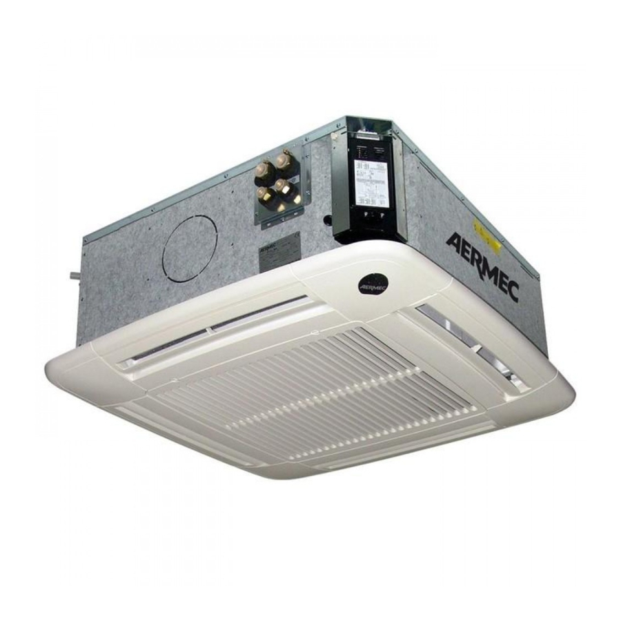
Cassette-type fan coil with inverter, 600x600/840x840
Hide thumbs
Also See for FCLI 32:
- Installation manual (76 pages) ,
- Use and installation manual (59 pages) ,
- Technical manual (55 pages)
Advertisement
Quick Links
Download this manual
See also:
Technical Manual
VENTILCONVETTORE CASSETTE CON INVERTER
FCLI
FCLI 32 (600x600)
FCLI 34 (600x600)
FCLI 42 (600x600)
FCLI 44 (600x600)
FCLI 62 (600x600)
FCLI 64 (600x600)
Please fill out the requested information
Please fill out the requested information
M A N U A L E I N S TA L L A Z I O N E
I N S T A L L A T I O N
M A N U E L D ' I N S T A L L A T I O N
I N S TA L L AT I O N S H A N D B U C H
M A N U A L
I N S T A L A C I Ó N
FCLI 82 (840x840)
FCLI 122 (840x840)
FCLI 124 (840x840)
IFCLIIJ_2104_5190705_00
M A N U A L
Advertisement

Related Manuals for AERMEC FCLI 32


Summary of Contents for AERMEC FCLI 32
- Page 1 I N S TA L L AT I O N S H A N D B U C H M A N U A L I N S T A L A C I Ó N VENTILCONVETTORE CASSETTE CON INVERTER FCLI FCLI 32 (600x600) FCLI 82 (840x840) FCLI 34 (600x600) FCLI 122 (840x840) FCLI 42 (600x600)
- Page 2 INDEX Important information • Maintenance • Packaging Operation • Use Description • Versions • Operating limits Main components • Description of components Installation information Unit installation Installing and replacing the filter Plumbing connections Condensate discharge connections External air suction connection Connection for air delivery in an adjacent room Electrical connections Dimensions...
- Page 3 If the supply cord is damaged, it must be avoid differences over 7°C between the replaced by the manufacturer, its service outdoor temperature and the tempera- WARNING: the fan coil is con- agent or similarly qualified persons in ture inside the room in summer. nected to the power supply and a water order to avoid a hazard.”...
- Page 4 The operating instructions can be found in the manual supplied with the control panel (GLLI100) (GLLI100N) (GLLI100) (GLLI100N) (GLLI100EH) In heating operation, a fin opening of In cooling operation, a fin opening of When the fins are closed ventilation is 20°...
- Page 5 Cassette-type fan coil with Inverter for installation in suspended ceilings; can be integrated in standard 600x600 and 840x840 panelling. AVAILABLE SIZES The cassette-type fan coils of the FCLI range are available in: for 2-pipe systems For 4-pipe systems FCLI 32 (600x600) FCLI 34 (600x600) FCLI 42 (600x600) FCLI 44 (600x600) FCLI 62 (600x600) FCLI 64 (600x600)
- Page 6 1 Grille with air filter (GLLI) 6 Base unit 11 Air drain valve 2 Air delivery deflector (GLLI) 7 Fastening brackets 12 Push-out, coupling for air delivery in an 3 Grille frame (GLLI) 8 Electrical box adjacent room Tray Water connections (only for 4 pipes) 13 Condensate drain 5 Inverter device 10 Water connections (2 pipes)
-
Page 7: Installation
drain valves, located respectively on the of the condensate that is produced by were developed in order to have the highest and lowest point of the battery the unit and deposited in the polysty- best possible distribution of the air, both circulation. - Page 8 Module "600" Module "840" Max. dimensions of water connections Condensate drain Max. dimensions of installation bracket side Max. dimensions of Max. dimensions of installation bracket installation bracket Max. dimensions of water connections Max. dimensions of installation bracket Max. dimensions of installation bracket Max.
- Page 9 - The grille frame must be positioned so support bracket by means of the nuts so disassembly phases that the glass with the AERMEC logo is in that the unit is level and the frame rests - connect the Inverter to the electric box, line with the corner of the electric box.
- Page 10 - The grille frame must be positioned so - remove the box that the glass with the AERMEC logo is in - remove the packaging shells used to line with the corner of the electric box. protect the unit during transport - Fix the grille with the 4 screws.
- Page 11 - remove the screw that blocks the corner - carry out the maintenance work If you need to access the electric box for hatch (with the Aermec logo) - reassemble everything, following the maintenance purposes, observe the fol- - remove the 2 screws that block the elec-...
- Page 12 The water connections are made with the hot water coil; use the supplied gaskets. instruction booklet. flat fittings complete with seal gaskets The accessory comes complete with gaskets The delivery and return pips must be equal, (supplied). for connection to the system. suitably scaled and insulated to avoid In the 4-pipe version of the unit, it is Information for the correct installation of...
- Page 13 During cooling operation the indoor device must never be interrupted. SC1 = Condensate discharge (male Ø 16mm) unit removes humidity from the air. The In the event of an alarm, the float device SC2 = Condensate discharge with siphon (male condensate water must be eliminated interrupts the flow of water in the coil.
- Page 14 • • SOLUZIONE • • • SOLUTION • ABHILFE SOLUCIÓN Scegliere la velocità corretta sul pannello comandi. Poca aria in uscita. Errata impostazione della velocità sul pannello comandi. Select the speed on the control panel. Feeble air discharge. Wrong speed setting on the control panel. Choisir la vitesse sur la panneau de commandes.
Need help?
Do you have a question about the FCLI 32 and is the answer not in the manual?
Questions and answers