Life Fitness Club Machine Assembly Instructions Manual
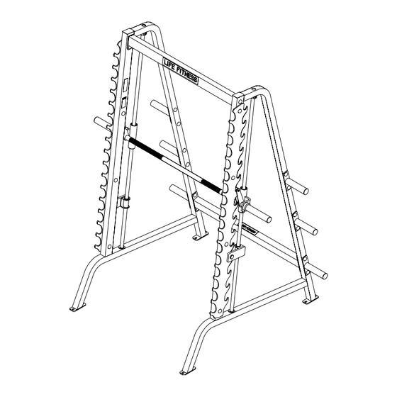
Club series smith machine
Hide thumbs
Also See for Club Machine:
- User manual (48 pages) ,
- Operation manual (26 pages) ,
- Assembly instructions manual (11 pages)

Related Manuals for Life Fitness Club Machine


Summary of Contents for Life Fitness Club Machine
-
Page 1: Assembly Instructions
CLUB SERIES SMITH MACHINE ASSEMBLY INSTRUCTIONS Part # 7187601 Revision:12/4/01 Rev. B... -
Page 2: Parts List
PART # DESCRIPTION 71851xx RIGHT UPRIGHT 71124xx TOP CROSS BRACE 71125xx BOTTOM CROSS BRACE 7185201 HOUSING 7182702 BAR STOP 3203002 1” SHAFT COLLAR 7185001 SMITH BAR 7178101 BAR SUPPORT RACK 7112601 WEIGHT HORN 7104601 GUIDE ROD The XX represents the color code for a part: 08 Ramsey White 07 Platinum NOTE: BOLT LENGTH IS MEASURED FROM THE UNDERSIDE OF THE HEAD OF THE BOLT. - Page 3 11 3/8 X 2-3/4” BOLT 3/8” LOW HEIGHT LOCK 12 3/8 X 3” BOLT 3/8” SAE RH CAP WASHER (BLACK/WHITE/PLATINUM) WASHER...
- Page 4 FIGURE 1 STEP 1: • LOOSELY assemble the two WEIGHT HORNS (9) and the BOTTOM CROSS BRACE (3) to the RIGHT and LEFT UPRIGHTS (1 & 16) as shown in FIGURE 1 using using four BLACK RH CAPS (18), four RH CAPS (19), four 3/8 X 3” BOLTS (12), eight 3/8” SAE WASHERS (14), eight 3/8”...
- Page 5 11 3/8 X 2-3/4” FIGURE 2 STEP 2: • SECURELY assemble the four WEIGHT HORNS (9) to the RIGHT and LEFT UPRIGHTS (1 & 16) as shown in FIGURE 2 using using eight BLACK RH CAPS (18), eight RH CAPS (19), eight 3/8 X 2-3/4” BOLTS (11), sixteen 3/8” SAE WASHERS (14), sixteen 3/8”...
- Page 6 !! IMPORTANT !! REMOVE TAPE FROM BOTH ENDS OF THE HOUSINGS AS SHOWN! DO NOT REMOVE PLASTIC TUBES ON THIS STEP! HOUSING FIGURE 3 STEP 3: • Insert the shaft of the HOUSINGS (4) into the ends of the SMITH BAR (7) as shown in FIGURE 3.
- Page 7 FIGURE 4 STEP 4: • Hook the SMITH BAR (7) onto slots of the BAR SUPPORT RACKS (8). • Slide one GUIDE ROD (10) through the upper hole in the UPRIGHT (1 & 16) and proceed to slide one 1” SHAFT COLLAR (6) over the bottom of the GUIDE ROD (10) as shown in FIGURE 4.
- Page 8 FIGURE 5 STEP 5: • Slide the 1” SHAFT COLLARS (6) up the GUIDE RODS (10) to the bushing of the UPRIGHTS (1 & 16) and SECURELY TIGHTEN. SECURELY TIGHTEN!
- Page 9 FIGURE 6 STEP 6: • If necessary, apply the FOREIGN LANGUAGE PLACARD LABEL (17) to the PLACARD LABEL on the RIGHT UPRIGHT (1) as shown in FIGURE 6. • This equipment is designed to be stable during normal use, however, in order to ensure the saftey of personnel during potential misuse of the equipment, we strongly recommend that this equipment be securely fastened to the floor of the facility with 1/2”...
-
Page 10: Warranty Information
There is a risk assumed by individuals who use this type of equipment. To minimize risk, please follow these rules: 1. Inspect equipment daily. Tighten all loose connections and replace worn parts immediately. Failure to do so may result in serious injury. 2.
Need help?
Do you have a question about the Club Machine and is the answer not in the manual?
Questions and answers