
Related Manuals for Life Fitness CM3


Summary of Contents for Life Fitness CM3
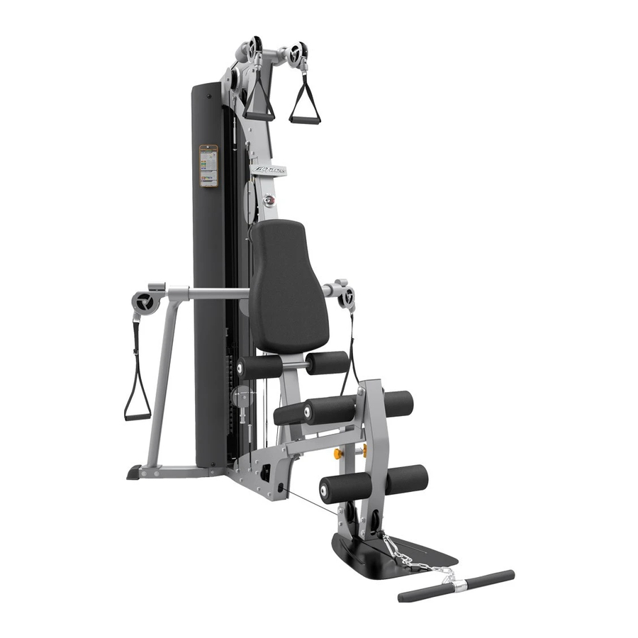
- Page 1 CLASS H PART # 7657801 REV. B CM3 GYM SYSTEM USER’S GUIDE WARNING: Read and follow all directions for each step to ensure proper assembly of this product. Version: CM3-108 Revision: 12/08/06...
- Page 2 7. Inspect cables and their connections before using machine. Pay particular attention to the cable ends. DO NOT attempt to fix any problems. Notify your authorized Life Fitness dealer and have repairs made by an authorized service technician before use.
- Page 3 MPORTANT OTES Thank you for purchasing the Life Fitness CM3 Gym System. Please read these instructions thoroughly and keep them for future reference. This product must be assembled on a flat, level surface to assure its proper function. DO NOT securely tighten any frame connections until the entire frame has been assembled, unless otherwise stated.
- Page 4 1’ 2’ 3’ 4’ 5’ 6’ 7’ 8’ 9’ CM3 F OOTPRINT = 1' QUARE INIMUM EQUIRED Length = 90 inches (229 cm) 7' 6" Width = 103 inches (262 cm) 8' 7" Height = 84 inches (213.5 cm) 7'...
- Page 5 ACU04-1165 WEIGHT STACK SPACER ACU04-1171 3-1/2" CABLE GUARD ACU04-1342 4-1/2" CABLE GUARD ACU05-0212 SHAFT COLLAR ACU06-0051 3-1/2" PULLEY ACU04-1213 CM3 Acc. Bar Adapter (Black) See paperclip Qty Key Part # Description ACU06-0035 4-1/2" PULLEY ACUKN000097 QUICK CONNECT ACU11-0068 T-HANDLE SPRING PIN...
- Page 6 ABLING IAGRAM ABLE SSEMBLY Slide parts onto cable in the following order: Item 2, Item 4, Item 3. Insert cable end into Item 1. Slide entire assembly over Item 1 and secure it by screwing one Item 5 into both sides of Item 2 and tightening.
- Page 7 ABLING IAGRAM P13-0112-2...
- Page 8 ABLING IAGRAM P13-0112-1...
- Page 9 ABLING IAGRAM P13-0112-5...
- Page 10 ABLING IAGRAM P13-0112-4...
- Page 11 IGURE A. Loosely assemble two Base Plates (11) to the Front Base (1) and the Base Connector (3) using four 3/8 x 3-3/4" Bolts (57) and four 3/8" Lock Nuts (13). See Figure 1. B. Loosely assemble the Footplate (66) to the Front Base (1) using one 3/8 x 3" Bolt (67) and one 3/8"...
- Page 12 A. Loosely assemble the Right Arm (5) and Rear Base (4) using two 3/8 x 3-3/4" Bolts (57), two 3/8" Washers (64) and two 3/8" Lock Nuts (63). B. Loosely assemble the Left Arm (66) and Rear Base (4) using two 3/8 x 3-3/4" Bolts (57), two 3/8" Washers (64) and two 3/8"...
- Page 13 Make sure that the Weight Plates (21) are assembled as shown in Figure 3 and the Head Plate Assembly (23) is assembled as shown in Figure 4. IGURE IGURE...
- Page 14 A. Insert two Guide Rods (18) into the Rear Base (4) as shown in Figure 5. (Note: If you purchased the CM3 Shroud Option, place the Guide Rods (18) through the Bottom Shroud Bracket (found in Shroud Option box) and into the Rear Base (4) as shown in Figure 5.) B.
- Page 15 A. Swing the Guide Rods (18) into the guide rod bushings in the Right Boom Plate (14) and Left Boom Plate (15) as shown in Figure 6. B. Loosely assemble the Right Boom Plate (14) and Left Boom Plate (15) to the Upright (2) using three 3/8 x 3-3/4"...
- Page 16 1/2 X 104mm A. Securely assemble the Three Prong Knob (43) to the Front Base (1) as shown. B. Insert the Seat Adjust Assembly (7) into the Front Base (1) as shown. The seat height can be adjusted using the Spring Pin and can be secured with the Three Prong Knob (43). C.
- Page 17 A. Detach Short Cable from both Rear Guide Cables (74) as shown in Figure 9 (B). B. Slide Long Cables of Rear Guide Cables (74) through eyelets of Guide Bracket (42) as shown in Figure 9 (B). Reattach Short Cable of Rear Guide Cables (74) to Long Cable, leaving Guide Bracket (42) loose.
- Page 18 MPORTANT NCOIL AND STRAIGHTEN ALL CABLES TO REMOVE ALL TWISTS BEFORE INSTALLING A. Assemble the Weight Stack Pin (27) to the Head Plate Assembly (23) as shown in Figure 10. B. Screw the long threaded end of the Weight Stack Cable (29) into the end of the Head Plate Assembly (23).
- Page 19 A. Loop the Weight Stack Cable (29) around one 3-1/2" Pulley (37). B. Assemble the 3-1/2" Pulley (37) with the Weight Stack Cable (29) around it to the Boom Plates (14 & 15) using one 3/8 x 4-1/4" Bolt (68), two 3/8" Flat Washers (64), two Guide Cables (65), two 3/8 x 1"...
- Page 20 IGURE A. Loop the Boom Cable (32) around one 3-1/2" Pulley (37). B. Assemble the 3-1/2" Pulley (37) with the Boom Cable (32) looped around it to the Guide Bracket (42), using one 3/8 x 1-3/4" Bolt (53) and one 3/8" Lock Nut (63).
- Page 21 A. Securely assemble the ball end of the Leg Cable (30) and one 3-1/2" Pulley (37) to the Leg Pedestal (8), using two 3/8 x 3-3/4" Bolts (57), two 3/8 x 1-1/16" Flange Spacers (49), two 3/8" Flat Washers (64) and two 3/8" Lock Nuts (63). Note: The Leg Cable (30) must be routed over the retaining bolt as shown in Figure 13.
- Page 22 A. Securely assemble one 3-1/2" Pulley (37) to the Pulley Plates (10), using one 3/8 x 1-3/4" Bolt (53) and one 3/8" Lock Nut (63). Note: Loop the Leg Cable (30) over the Pulley before assembling the Pulley Plates, as shown in Figure A.
- Page 23 IGURE A. Route the Arm Cable (31) through the Left Arm (6) as shown in Figure 16. B. Loop the Arm Cable (31) around one 4-1/2" Pulley (38). C. Securely assemble the 4-1/2" Pulley (38) with the Arm Cable (31) around it to the Left Arm (6), using one 3/8 x 2"...
- Page 24 A. Securely assemble two 3-1/2" Pulleys (37) to the Base Plates (11), using two 3/8 x 3-3/4" Bolts (57), one 3/8 x 1" Spacer (51) and two 3/8" Lock Nuts (63). B. Loop the Arm Cable (31) between the two Pulleys (37) around one 3-1/2" Pulley (37) as shown in Figure 17.
- Page 25 IGURE A. Route the Arm Cable (31) through the Right Arm (5) as shown in Figure 18. B. Loop the Arm Cable (31) around one 4-1/2" Pulley (38). C. Securely assemble the 4-1/2" Pulley (38) with the Arm Cable (31) around it to the Right Arm (6), using one 3/8 x 2"...
- Page 26 IGURE A. Insert Arm Cable (31) ends through Swivel Pulley Assemblies (72). B. Insert Swivel Pulley Assemblies (72) into Left Arm (5) and Right Arm (6). C. Secure Swivel Pulley Assemblies (72) in Left Arm (5) and Right Arm (6) using one C-Ring (12) each.
- Page 27 IGURE 1/2 X 5-3/4” A. Securely assemble one Seat Pad (16) to the Back Pad Adjustment (71) using two 3/8 x 1-1/4" Bolts (70) and two 3/8" Washers. B. Securely assemble the Back Pad Adjustment (71) to the Upright (2), using one 1/2 x 5-3/4" Bolt (61) and one 1/2"...
- Page 28 E. For maximum performance, the Head Plate (23) should just barely sit on the Weight Plate (21). F. After making adjustments, make sure all jam nuts are securely tightened. This completes the assembly of the CM3 Gym System. To add the CM3 Shroud Option (purchased seperately), refer to the CM3 Shroud Kit Assembly Instructions.
- Page 29 AINTENANCE We recommend cleaning your product (pads and frame) on a regular basis, using warm soapy water. Touch-up paint can be purchased from your Life Fitness customer service repre- sentative at 1-800-351-3737. Inspect equipment daily. Tighten all loose connections and replace worn parts immediately.
- Page 30 1. LIMITED WARRANTY ON FRAME AND WELDS. If the frame of the Life Fitness product or a weld should crack or break, it will be repaired or replaced by Life Fitness. Terms: Lifetime – for so long as the Customer owns the Life Fitness product.
- Page 31 800.351.3737 (Toll-free within U.S.A., Canada) ITNESS ACIFIC Room 2610, Miramar Tower 132 Nathan Road Tsimshatsui, Kowloon HONG KONG Telephone: (+852) 2891.6677 FAX: (+852) 2575.6001 ITNESS TLANTIC ITNESS ENELUX Bijdorpplein 25-31 2992 LB Barendrecht THE NETHERLANDS Telephone: (+31) 180.646.666 FAX: (+31) 180.646.699 ITNESS ENELUX Parc Industriel de Petit-Rechain...
Need help?
Do you have a question about the CM3 and is the answer not in the manual?
Questions and answers