Table of Contents
Advertisement
Advertisement
Table of Contents

Related Manuals for RCS TR65


Summary of Contents for RCS TR65
- Page 1 Model TR65 RS485 Thermostat OPERATION MANUAL DCN: 141-02165-01 5/03/12...
- Page 2 RS485 Thermostat This manual applies to the following product revisions or later revisions up to the next manual revision release: Product Part No: Firmware Revision TR65 RS485 Thermostat 001-02165 Includes TS65 Wall Display Unit 001-02102 ZCV1 HVAC Control Unit 001-01065...
-
Page 3: Table Of Contents
Table of Contents Overview ..............................4 Thermostat Control Screen ........................5 Temperature Display ..........................5 Setpoint Display ............................6 Thermostat Operation Buttons ........................6 Pressing these buttons will take you to the following screens: ..............6 Setpoint Up/Down Buttons ......................... 6 Press either the Up or Down buttons to go to the Heating or Cooling Setpoint screen. -
Page 4: Overview
The TR65 thermostat provides typical thermostat control of a central heating and cooling HVAC system plus has the added feature of RS485 communications for remote control. The TR65 is a two part thermostat with a Wall Display Unit and a HVAC Control Unit. -
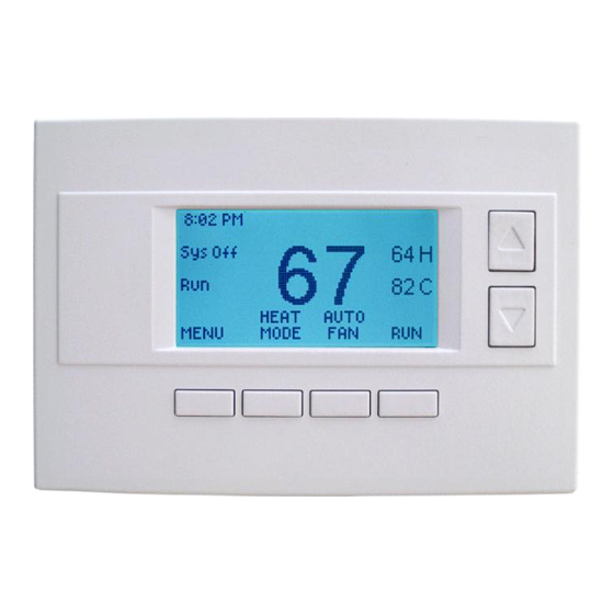
Page 5: Thermostat Control Screen
Thermostat Control Screen Minimized Screen The Minimized Screen shows only the room temperature. It is displayed if you set the “Screen Timeout” in the User Settings Menu to a time greater than 0. If set to 0, the minimized screen is disabled, and the main thermostat screen is normally displayed Press any button to return to... -
Page 6: Setpoint Display
Setpoint Display The current heating and cooling setpoints are displayed next to the Setpoint Up/Down buttons. Thermostat Operation Buttons Pressing these buttons will take you to the following screens: Menu – go to the Main Menu Screen to select other thermostat settings screens. -
Page 7: Heating/Cooling Setpoint Setting
Heating/Cooling Setpoint Setting Setting Heating or Cooling Setpoints Setpoint Up and Down Buttons Press either the Up or Down button in the main Thermostat Control Screen to go to the current system operating mode (Heating or Cooling) Setpoint screen, as shown below. Heating /Cooling Setpoint Adjustment Screen HEATING SETPOINT Heating and Cooling... -
Page 8: System Mode
System Mode Setting the System Mode In the main Thermostat Control Screen, press the System Mode button to display the System Mode selection screen, as shown below. Select the mode desired with the Up/Down buttons. Press the Done button to select and exit. System Mode Screen SYSTEM MODE Select system mode... -
Page 9: Fan Mode
Fan Mode Setting the Fan Mode The FAN button controls the HVAC system’s MANUAL fan mode. The current manual fan mode is displayed above the button, Auto or On. Normally the FAN mode is in the Auto mode (the system fan is automatically controlled by HVAC system). If you want the FAN on manually, select the ON mode. -
Page 10: Schedule Operation
Schedule Operation Setting the Schedule Mode The Schedule button sets the schedule operation to RUN or HOLD mode. It also allows you to select three different setback modes, HOME, AWAY and VACATION. Pressing the Schedule button in the main Thermostat Control Screen will take you to the SCHEDULE MODE menu screen as shown below. -
Page 11: Main Menu
For these to show up in the main menu list, they must be enabled in the Installer Settings. SmartVent. Control screens for the optional SmartVent fresh air venting system. Messaging. A messaging system to send messages to the TR65 via the RS485 network. -
Page 12: Main Menu - Schedules
Main menu - Schedules Thermostat Schedule Selection The thermostat has a day and time heating and cooling setpoint temperature adjustment scheduler. It provides a 4x7 schedule, which has four times a day for each day of the week, for which separate heating and cooling setpoints can be programmed. -
Page 13: Main Menu - Schedules - Heat And Cool Schedule Screen
Main Menu - Schedules - Heat and Cool Schedule Screen Schedule Edit Screen When you select the Heat and Cool menu item in the Schedules screen, the “day” schedule programming screen opens and the schedule for the current day will be displayed. You can navigate around to the time and setpoint temperatures in each of the four daily time groups, and adjust as desired. -
Page 14: Main Menu - Schedules - Heat And Cool - Copy Schedule
Main Menu - Schedules - Heat and Cool - Copy Schedule Copying a Day Schedule to another Day The Copy Schedule screen allows you to copy one day’s schedule to another day or group of days. First select the day to be copied in the previous Heat and Cool, Edit Schedule screen. Scroll to the “c” at the bottom of the day’s Schedule screen to highlight it. -
Page 15: Main Menu - User Settings
Main Menu - User Settings The User Settings screen allows you to set or change various user options of the thermostat such as the Clock, Filter and Maintenance service timers, Minimized Screen timeout, Fahrenheit/Celsius mode, Sensor Calibrations, and Display settings. User Settings Screen User Settings Select menu item with... -
Page 16: Main Menu - User Settings - Set Clock
Main Menu - User Settings - Set Clock The Set Clock screen allows you to set the Thermostat’s internal clock. To set the Time and Date, move the cursor with the navigation arrows until the data you want to change is highlighted. -
Page 17: Main Menu - User Settings - Filter Service
Main Menu - User Settings - Filter Service The Filter Service screen will show the accumulated Filter Runtime hours as well as the Service Interval that will be used to trigger a Filter Message. Any type of HVAC operation that causes the HVAC system fan to run will cause the Filter Runtime value to increase. -
Page 18: Main Menu - User Settings - Maint Service
Main Menu - User Settings - Maint Service The Maintenance Service screen will show the accumulated Heat and Cool Runtime hours as well as the Service Interval that will be used to trigger a Maintenance Message. Any HEAT or COOL type of HVAC operation will cause the respective Runtime values to increase. -
Page 19: Main Menu - User Settings - Sensor Calibration
Main Menu - User Settings - Sensor Calibration The Sensor Calibration screen allows you to change the temperature calibration of the internal temperature sensor, aremote sensor or the outside sensor. You can change the temperature calibration by +/- 7 degrees. When the Sensor Calibration screen is selected it will show the current temperature calibration of the internal and any connected remote or outside sensors. -
Page 20: Main Menu - User Settings - Backlite/Display
Main Menu - User Settings - Backlite/Display The Backlite/Display screen allows you to set the Backlite timeout and contrast. Backlite Timeout: Sets the time from last button press that the backlite will timeout and turn off. The timeout value is adjustable from 0 or 20 to 120 seconds. If set to “0”, the Backlite will always be ON. If set in the range of 20 to 120 seconds, the Backlite will turn OFF after the selected time expires. -
Page 21: Main Menu - Thermostat Info
Main Menu - Thermostat Info The Thermostat Info screen displays the current configuration of the TR65 Thermostat. This information is useful for quick check of firmware versions and HVAC system setup. It also shows the network address setting. Setup information can only be viewed on this screen and not changed. The HVAC system setup is set by the dipswitch SW1 on the HVAC Control Unit. -
Page 22: Main Menu - Smartvent (Optional)
Main Menu – SmartVent (optional) Note: this is an optional feature of the TR65. It must be enabled in the “Installer Settings” menu to appear in the Main Menu list. Go to Installer Settings/SmartVent to enable SmartVent. SmartVent is an automatic fresh air ventilation system. It provides manual, timed, scheduled and automatic ventilation. - Page 23 Smart Vent Control Screen The Smart Vent control screen shows the current Smart Vent information and allows you to select operating modes and other functions. The screen information and controls are shown below. Timed Vent Time remaining indicator 0:30 SMART VENT INSIDE SETPOINT Vent ON indicator...
- Page 24 Smart Vent Setup Screen SMARTVENT SETUP Sched ON/OFF Cursor Schedules navigation buttons DONE SELECT Select “Schedule ON/OFF” to set the vent schedule to “ON” or “OFF” mode by using the +/- buttons. Select “Schedules” to go to the Smart Vent Schedule Screen to enter Schedule Start and Run times. Smart Vent Schedule Screen Smart Vent Schedule Start Time...
-
Page 25: Main Menu - Messaging (Optional)
Main Menu – Messaging (optional) Note: this is an optional feature of the TR65. It must be enabled in the “Installer Settings” menu to appear in the Main Menu list. Go to Installer Settings/WDU options to enable Messaging. Messaging The TR65 thermostat has the option to receive and display text messages up to 80 characters in length via the RS485 network. -
Page 26: Installer Settings Screen
0 is reserved for host address, 255 is a global address. Network Type: Range: RCS or CDX Default: RCS Protocol type selection: RCS is normal. CDX is a special protocol for direct connection to a GE NetworX NX8E security panel. Autosend: Range: Y or N Default: N In autosend mode, the thermostat will transmit any changes in temperature, setpoints or modes. - Page 27 Stage Settings Submenu Range: 0 – 30 minutes H1 Stage Up Default: 0 (0=disabled) If setpoint is not met by the stage up time, a forced stage up to stage 2 heating occurs. Range: 0 – 30 minutes H2 Stage Up Default: 0 (0=disabled) If setpoint is not met by the stage up time, a forced stage up to stage 3 heating occurs Range: 0 –...
- Page 28 H/C Delta Range: 0 - 15 degrees. Default: 4 Sets the minimum separation between heating and cooling setpoints. Attempts to lower the cooling below the heating setpoint by this amount will PUSH the heating setpoint down to maintain this separation. Same for setting the heating setpoint above the cooling setpoint, it will PUSH the cooling setpoint up to maintain this separation.
Need help?
Do you have a question about the TR65 and is the answer not in the manual?
Questions and answers