Table of Contents
Advertisement
Advertisement
Table of Contents

Related Manuals for RCS TZ43


Summary of Contents for RCS TZ43
-
Page 1: Zwave Thermostat
Model TZ43 ZWave Thermostat INSTALLATION OPERATION MANUAL DCN: 141-01652-04 10/06/08 *** IMPORTANT NOTICE *** DO NOT USE THIS PRODUCT FOR BUILDING FREEZE PROTECTION! YOU ARE ADVISED TO INSTALL A MECHANICAL FREEZE PROTECTION DEVICE ON YOUR SYSTEM FOR THIS PURPOSE. - Page 2 Model: TZ43 ZWave Thermostat This manual applies to the following product revisions or later revisions up to the next manual revision release: Product Part No: Firmware ZWave Thermostat 001-01652 Document Revision History Revision Date Changes 7/30/08 Original release 8/22/08 Updated Zwave Install description...
-
Page 3: Table Of Contents
Remote Temperature Sensors ........................ 30 Power............................... 31 Standard Gas/Electric HVAC System Wiring ..................32 Heat Pump HVAC System Wiring ......................33 HVAC SYSTEM QUICK TEST ........................34 ZWave Command Class Information....................... 36 TZ43 Variable Table ..........................36 DCN 141-01128-04 10/6/08... -
Page 4: Overview
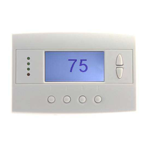
Overview TZ43 Thermostat The TZ43 thermostat provides for typical thermostat control of a central heating and cooling HVAC system plus has the added feature of ZWave communications for remote control. The thermostat has a large, backlit graphical display, control buttons, status LEDs and a temperature sensor. -
Page 5: Z-Wave® Programming And Operation
Z-wave® Programming and Operation Z-Wave controllers from various manufacturers may support the Z-Wave Thermostat General V2 Device class used by the RCS TZ43 Thermostat. The following procedure will allow the thermostat to be added to a Z-Wave network. General Programming Procedure (for controllers supporting the thermostat device class): 1. -
Page 6: Operation
Operation Thermostat Control Buttons The Thermostats buttons are “Soft Keys” meaning that they change functions when you change screens. The function of the button is defined by “on-screen labels” that are dynamic and change when you change screens. LEDs The Thermostat has four LED’s that displays status information. The LEDs have dynamic “on-screen” labels that can change with the screen being displayed. -
Page 7: Thermostat Control Screen
Thermostat Control Screen 10:25 AM Outside 60 Sys Off 76 H Economy 74 C No Msg MENU MODE The thermostat control screen is the default display screen and is the screen that is normally displayed on the Thermostat. It can be set to switch to a minimized screen of only room temperature after a few seconds of display. -
Page 8: Thermostat Control Screen Buttons
Thermostat Control Screen Thermostat Control Screen Buttons UP and DOWN Buttons The UP and DOWN buttons adjust the setpoint temperature. Pressing the UP button will increment the setpoint value by one degree and conversely, pressing the Down button will decrement the setpoint one degree. Pressing and holding a button down will cause the setpoint to continuously change until the button is released. - Page 9 Thermostat Control Screen Mode Button Operation Off Mode: System is off. No heating or cooling will come on. If system was on, it will turn off. Heat Mode: Only heating will occur. Cool Mode: Only cooling will occur. Auto Mode: Heating or cooling will come on according to the heating and cooling setpoints. The system will automatically switch between heating and cooling when the temperature exceeds the appropriate setpoints.
-
Page 10: Led Displays
Thermostat Control Screen LED Displays The Thermostat Control Screen has the following LED labels and descriptions, numbered from top to bottom, 1-4. LED 1 Green: System Operation display. LED Off, “SYS OFF” displayed > HVAC system is OFF LED Off, “SYS MOT” displayed > Minimum Off Time (MOT) delay on is active LED On, “SYS ON”... -
Page 11: Main Menu
Main Menu The Thermostat has a menu tree that can be accessed by pressing the “Menu” button on the Main Thermostat screen. Various configurations of the Thermostat can have different screen contents. The first screen that will come up is the Main Menu screen. This is a list of the other menus or functions that can be accessed. -
Page 12: Schedules Screen
Main menu - Schedules The Schedules Screen allows you to review and set the setback schedule for the thermostat. The thermostat has a 4 x 7 schedule. Four times a day can be selected for changes to the heating and cooling setpoints. - Page 13 Main Menu - Schedules - Heat and Cool Schedule Screen When you select the Heat and Cool Schedule menu item, the “day” Schedule programming screen opens and the schedule for current day will be displayed. Use the scroll buttons to highlight the data to be modified.
- Page 14 Main Menu - Schedules - Heat and Cool - Copy Schedule The Copy Schedule screen is a sub screen of the Schedule screen. The Copy Schedule screen allows you to copy a day’s schedule to another day or group of days. First select the day to be copied in the Schedule screen.
-
Page 15: User Settings Screen
Main Menu - User Settings The User Settings screen allows you to set or change various user options of the thermostat such as the Clock, Minimized Screen timeout, Fahrenheit/Celsius mode, Sensor Calibrations, and Display settings. Menu options: Set Clock: Select this menu item to go to the Clock setting screen. Filter Service: Sets/resets the filter timer/alert. - Page 16 Main Menu - User Settings - Set Clock The Set Clock screen allows you to set the Thermostat’s internal clock. To set the Time and Date, move the cursor with the navigation arrows until the data you want to change is highlighted.
- Page 17 Main Menu - User Settings - Filter Service The Filter Service screen will show the accumulated Filter Runtime hours as well as the Service Interval that will be used to trigger a Filter Message. Any type of HVAC operation that causes the HVAC system fan to run will cause the Filter Runtime value to increase.
- Page 18 Main Menu - User Settings - Maint Service The Maintenance Service screen will show the accumulated Heat and Cool Runtime hours as well as the Service Interval that will be used to trigger a Maintenance Message. Any HEAT or COOL type of HVAC operation will cause the respective Runtime values to increase.
-
Page 19: Sensor Calibration Screen
Main Menu - User Settings - Sensor Calibration The Sensor Calibration screen allows you to change the temperature calibration for the internal and any external remote temperature sensors attached to the Thermostat. You can change the temperature calibration by +/- 7 degrees. When the Sensor Calibration screen is selected it will show the internal and all detected remote sensors. - Page 20 Main Menu - User Settings - Backlite/Display The Backlite/Display screen allows you to set the Backlite ON and OFF brightness levels and contrast. Backlite Timeout: Sets the time from last button press that the backlite will timeout and turn off. The timeout value is adjustable from 0 or 20 to 45 seconds.
-
Page 21: Thermostat Info Screen
Main Menu - Thermostat Info The Thermostat Info screen displays the current configuration of the TZ43 Thermostat. This information is useful for quick check of firmware versions and HVAC system setup. It also shows the Zwave network setting. Thermostat information displayed is: Thermostat - Model and firmware version number. -
Page 22: Main Menu > Installer Settings (Hidden Screen)
Main Menu > Installer Settings (Hidden Screen) The Installer Settings screen is a hidden screen designed for installer use only. Do not change any settings in this screen unless you are a qualified service technician. Changing these settings will affect the operation of the heating/cooling system. -
Page 23: Minimum Run Time
Note: The Delta T Setting is the delta, or difference between, the setpoint and current temp for determining when a heat or cool call comes on. The “delta” is the number of degrees away from setpoint. H/C Delta Range: 3 - 15 degrees. Default: 4. - Page 24 Range: 0-120 minutes Default: 20 Remote Sensors Submenu The TZ43 can support 2 remote sensors, 10K Thermistor type. Each sensor can support several “Thermostat Curves”, the most common curves being the A-Curve, Type 2 and Type 3. RS1 Type Range: A Curve, Type 2, Type 3 Default: Type 2 Selects the 10K Thermistor curve for Remote Sensor 1.
-
Page 25: Installer Settings Summary
Installer Settings Summary Setting Range Default Display Lock Y or N Locks out front buttons Service Mode Y or N Turns on service mode shortens delays to 15 seconds. CAUTION no compressor protection. F/C Mode C or F Screen Timeout 0-240 seconds Schedule Override... -
Page 26: Installer Settings Screen
Installer Settings Screen Installer Settings Display Lock Service Mode System Settings Max Heat SP Select Done Screen navigation buttons: Done Return to Main Menu screen Move menu selection pointer up Increase by 1 or change from N to Y Decrease by 1 or change from Y to N Move menu selection pointer down Select Select menu item to go to a submenu... -
Page 27: Hvac System Connection
For Heat Pump HVAC systems, the HVAC outputs support 3 stages of heating (2 compressor/1 heatstrip) and 2 stages of cooling. Remote Communications The TZ43 thermostats have a Zwave communications module for communicating to control systems with Zwave capability. Outside Temperature Operation The thermostat can use and display outside temperature information from a sensor attached to the RS2 Remote Sensor connection The outside temperature will be displayed on the Thermostat. -
Page 28: Hvac System Operation And Setup
HVAC System Operation and Setup General Heating and Cooling Operation In the HEATING mode, the heating system will be turned on at one degree below the setpoint and will turn off at the setpoint. This turn on and turn off offset is referred to as the heating setpoint “delta T” and is adjustable in the Installer Settings menu of the THERMOSTAT. - Page 29 Minimum Run Time (MRT) The TZ43 has a Minimum Run Time after the start of any heat or cool call. This minimum run time assures even heating and cooling cycles. Minimum Run Time will keep the system on even if you change the setpoint to a temperature that would satisfy the call, until the MRT expires.
-
Page 30: Remote Temperature Sensors
INSTALLATION Remote Temperature Sensors The TZ43 can accept up to 2 remote temperature sensors. The first sensor (RS1) will replace the internal temperature sensor of the TZ43. The second sensor (RS2) can either be an averaging sensor or an Outside sensor. -
Page 31: Power
The TZ43 requires 24VAC power from the HVAC system it is controlling. Connect the 24VAC Common (typically the Blue wire/terminal) and 24VAC R (typically the Red wire/terminal) from the HVAC system to the TZ43’s HVAC System terminal block 24VCom and 24V RH or 24V RC terminals (the RH and RC terminals are default tied together) Common or Split Transformer Systems Most HVAC systems have a common heating and cooling transformer. -
Page 32: Standard Gas/Electric Hvac System Wiring
HVAC SYSTEM CONNECTION Standard Gas/Electric HVAC System Wiring TZ43 Thermostat Standard HVAC System THERMOSTAT CONNECTION 24COM BLUE 24RC C 24VAC COMMON 24RH R 24VAC RETURN WHITE W1 HEAT W 1 Heat Stage 1 W2/O ORANGE W2 Heat Stage 2 GREEN... -
Page 33: Heat Pump Hvac System Wiring
HVAC SYSTEM CONNECTION Heat Pump HVAC System Wiring Heat Pump HVAC System HVAC SYSTEM THERMOSTAT CONNECTION TZ43 BLUE 24COM C 24VAC COMMON 24RC 24RH R 24VAC RETURN WHITE W1 Heat W1 Aux Heat Stage 1 ORANGE W2/CO O/B Changeover (CO) Valve... -
Page 34: Hvac System Quick Test
If you need to verify that the HVAC system is operational, you can perform the following test Thermostats, like the TZ43, are just switches to the HVAC system as shown in the diagram below. This is a simplified example of a thermostat and a standard HVAC wiring diagram. The HVAC system operation can be tested by duplicating the thermostat switch operation by shorting across the thermostat terminals on the HVAC system. - Page 35 In that case, cut Jumper JP1 and wire the heating transformer red wire to the RH terminal and the cooling system transformer red wire to the RC terminal. Wire the cooling system’s 24VAC Com to the TZ43’s 24VAC Com terminal. DCN 141-01128-04 10/6/08...
-
Page 36: Zwave Command Class Information
COMMAND_CLASS_THERMOSTAT_FAN_MODE The Fan Mode COMMAND_CLASS_THERMOSTAT_FAN_STATE The HVAC system mechanical fan state COMMAND_CLASS_SENSOR_MULTILEVEL Returns the temperature as displayed by the TZ43. Note this temperature is the TZ43’s working temperature and includes any averaging sensors COMMAND_CLASS_VERSION Returns various Zwave version information COMMAND_CLASS_CLOCK Used to set the TZ43’s real-time clock... - Page 37 DCN 141-01128-04 10/6/08...
Need help?
Do you have a question about the TZ43 and is the answer not in the manual?
Questions and answers