Table of Contents
Advertisement
Quick Links
RCS
Residential Control Systems Inc.
Communicating Thermostat
INSTALLATION AND OPERATION MANUAL
Product
TR16-485 Thermostat
TS16 Wall Display Unit
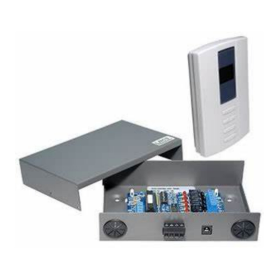
HFR-485 HVAC Control Unit
DO NOT USE THIS PRODUCT FOR BUILDING FREEZE PROTECTION! YOU ARE ADVISED TO
INSTALL A MECHANICAL FREEZE PROTECTION DEVICE FOR THIS PURPOSE.
Model TR16
With RS485 Communications
Rev P HVAC Control Unit
DCN: 141-00930-09
This revision of the document applies to the following part numbers and revisions or later.
Rev
P
G
P
*** IMPORTANT NOTICE ***
Rev 09
7/13/06
Part No
001-00930-30
001-00910-12
001-01430-03
Firmware
TS16v340
HFR3052
TR16 Operation
Advertisement
Table of Contents

Related Manuals for RCS TR16


Summary of Contents for RCS TR16
-
Page 1: Communicating Thermostat
Residential Control Systems Inc. Model TR16 Communicating Thermostat With RS485 Communications INSTALLATION AND OPERATION MANUAL Rev P HVAC Control Unit DCN: 141-00930-09 Rev 09 7/13/06 This revision of the document applies to the following part numbers and revisions or later. - Page 2 The TR16 has automatic detection and setup of remote temperature sensors. Remote sensors have address settings that, when detected by the TR16, will be used for specific functions, such as, in lieu of the internal sensor, averaging with other sensors.
-
Page 3: Lcd Display
TS16 Wall Display Unit The TS16 Wall Display Unit has a LCD display and control buttons for changing the setpoint, system operating mode and manual fan mode. The WDU also has an internal temperature sensor. The display serves as a common display for many functions. It normally shows the current room temperature but switches to show setpoint, mode or other functions when buttons are pushed. -
Page 4: Control Buttons
Control Buttons Setpoint UP and DOWN Buttons The UP and DOWN buttons control the heating or cooling setpoint temperature. TO VIEW THE CURRENT SETPOINT: Push either the UP or DOWN buttons once will cause the LCD display to change to show the current setpoint temperature (but won’t change it). TO CHANGE THE SETPOINT: With the setpoint displayed as above, push the UP button to increase the setpoint temperature by one degree or push the DOWN button to decrease the setpoint by one degree. -
Page 5: Setup Mode
Setting the Fahrenheit or Celsius mode In the setup mode, press the mode button to select “FC” mode. The TR16 is default set to F mode. To change the degree mode, press the UP/DOWN buttons to select F or C as desired. To exit press mode again to move another setup mode or wait for the screen to time out and return to the normal thermostat temperature display. -
Page 6: Remote Sensors
You can view the outside temperature by pressing both the UP/DOWN buttons simultaneously. Display Lock The TR16 WDU control buttons can be locked to prevent unauthorized changes in system operation from the WDU. The display lock/unlock state can only be set by the “DL” network command. See the Serial Protocol Manual for details on this command. -
Page 7: Hvac System Compatibility
The TR16 Control Unit connects to the HVAC system the same as, and in place of, a standard thermostat. It is usually mounted near the HVAC system, although it can be mounted anywhere convenient. It is connected to the WDU by a 4 wire cable, either standard thermostat wiring or typically Cat 3/5 in new construction. - Page 8 G, W1, W2 HEAT PUMP HVAC SYSTEM OPERATION The TR16 has Heat Pump operating modes of Heating, Cooling, Auto changeover and Emergency Heat. The Heat Pump HVAC system operation is the same as for Standard systems for normal first and second stage operations.
-
Page 9: Status Leds
CO relay will already be on and this avoids continuous on/off cycling the CO valve for each call. After the MOT period expires and another call is not active, the CO output will go OFF. TR16 Control Unit HVAC System Outputs for Heat Pump Systems Operating Mode... -
Page 10: Address Setting
1 to 254 is selected. The default address is 1. Serial Protocol The TR16 thermostat has a robust serial protocol. It is based on a simple ASCII message format as described in the RCS Serial Communications Protocol manual, DCN# 150-00225. -
Page 11: Installation Overview
TR16 Installation STOP Before proceeding with removing an existing thermostat and installing the TR16, Read the following important steps. 1. Record existing wiring information on the enclosed wiring form. 2. Perform the TR16 bench test 3. Check WDU wiring BEFORE applying power to control unit. - Page 12 TR16 Wall Display Unit Installation WDU Location Choose a location that best represents the temperature of the area to be controlled. Avoid locations that are subject to drafts, from doors and windows, or areas with direct sunlight exposure. WDU Mounting Route the wires to the WDU through the access hole in the back of the case. Mount the WDU to the wall with the screws and anchors provided.
-
Page 13: Location And Mounting
HVAC system but care should be taken to avoid the hot burner section or high vibration areas. Control unit wiring The TR16 HVAC Control Unit is connected to the HVAC system and to the Wall Display Unit as well as the serial communications and power connections. Control Unit to WDU wiring Connect the WDU to the Control Unit with existing thermostat wiring in retrofit installations. -
Page 14: Hvac System Wiring
IMPORTANT! For typical central heating/cooling systems, leave jumper JP1 installed. If you have separate Heating and Cooling system transformers, CUT JUMPER JP1. Wire TR16 Control Unit RC to the Cooling system transformer and RH to the Heating system transformer. FUSE... - Page 15 HVAC System Wiring Diagram 2 - Heat Pump System Wiring TR16 Control Unit FUSE IMPORTANT! Do not cut JP1 for Heat Pump Systems. RC and RH are common for Heat Pumps. Heat Pump HVAC System OFF ON Note: Set SW1-S1 to HP RC&RH...
- Page 16 TR16 Power Connection The TR16 Control Unit requires 24VAC power from the HVAC system it is controlling. Connect the 24VAC Common (typically the Blue wire/terminal) and 24VAC R (typically the Red wire/terminal) from the HVAC system to the control unit’s HVAC System terminal block J4’s 24VCom and 24V RH or 24V RC terminals (the RH and RC terminals are default jumpered together…see below)
- Page 17 WDU to update it’s display. TR16 thermostats also responds to request for status by serial commands and can provide all thermostat data and setup information as well as the current revisions of the WDU and Controller firmware.
-
Page 18: System Checkout
System Checkout It is strongly recommended that you hook-up and run a simple bench test before installing the TR16. Not only will this save you time in system checkout but will also familiarize you with the thermostat’s operation. THERMOSTAT BENCH TEST 1. -
Page 19: Hvac System Testing
(O) outputs. You must know what your system CO type is (CO with Cool (typical) or CO with Heat). You should have configured the TR16 control unit for correct CO type, refer to this setting. Heat Pump systems have an additional O terminal. - Page 20 TR16 Wiring Diagram TR16 CONTROL UNIT Fuse Mini ATO 2 Amp TS16 OFF ON WALL DISPLAY UNIT RH=RC Cut Jumper to split HVAC SYSTEM +12VDC +V Blue 24V COM STATUS THERMOSTAT CONNECTOR CLOCK 24V RH C - 24VAC Common HEAT1...
- Page 21 Appendix A TR16 Serial Network Command and Variable List Refer to the RCS Serial Communications Protocol Manual, DCN 150-00225 for details of message formats and commands. These may change with newer firmware versions. Network Message Format: Device Address, Originator (optional if address is 0), Command...
Need help?
Do you have a question about the TR16 and is the answer not in the manual?
Questions and answers