
Related Manuals for RCS TZ45


Summary of Contents for RCS TZ45
- Page 1 Model TZ45 Z-Wave Thermostat INSTALLATION OPERATION MANUAL DCN: 141-01773-02 1/19/11...
- Page 2 Model: TZ45 Z-Wave Thermostat This manual applies to the following product revisions or later revisions up to the next manual revision release: Product Part No: Firmware Revision Z-Wave Thermostat 001-01773 1.00.3 Document Revision History Revision Date Changes 10/20/10 Original release...
-
Page 3: Table Of Contents
Table of Contents Overview ..............................4 Z-Wave® Installation ........................... 5 Setback Mode Operation ........................... 5 Inclusion and Exclusion ..........................5 Thermostat Control Screen ........................6 Temperature Display ..........................6 Setpoint Display ............................6 Thermostat Operation Buttons........................7 Setpoint Up/Down Buttons ......................... 7 Clock Display ............................. -
Page 4: Overview
Overview Z-Wave Thermostat The Z-Wave thermostat provides for typical thermostat control of a central heating and cooling HVAC system plus has the added feature of Z-Wave communications for remote control. The thermostat has a large, backlit graphical display, control buttons, status LEDs and a temperature sensor. -
Page 5: Z-Wave® Installation
Sending the BASIC_SET (Value = 0xFF), the thermostat will revert back to the mode it was in (Hold or Run) before the BASIC_SET (Value = 0x00) command was sent. Note that when the BASIC_SET commands are sent, the TZ45 will momentarily display the new mode on the Schedule Mode screen. -
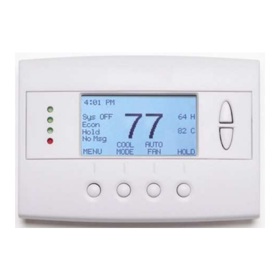
Page 6: Thermostat Control Screen
Thermostat Control Screen Minimized Screen The Minimized Screen shows only the room temperature. It is displayed if you set the “Screen Timeout” in the User Settings Menu to a time greater than 0. If set to 0, the minimized screen is disabled, and the main thermostat screen is normally displayed Press any button to return to... -
Page 7: Thermostat Operation Buttons
Thermostat Operation Buttons Menu – go to the Main Menu Screen to select other thermostat settings screens System Mode – go to the System Mode screen to set thermostat operating mode Fan Mode – go to the Fan mode screen to set the fan mode Schedule Mode –... -
Page 8: Setting Heating Or Cooling Setpoints
Heating/Cooling Setpoint Setting Setting Heating or Cooling Setpoints Setpoint Up and Down Buttons Press either the Up or Down button in the main Thermostat Control Screen to go to the current system operating mode (Heating or Cooling) Setpoint screen. as shown below. Heating /Cooling Setpoint Adjustment Screen HEATING SETPOINT Heating and Cooling... -
Page 9: System Mode
System Mode Press the System Mode button to display the System Mode selection screen. System Mode Screen SYSTEM MODE Select system mode HEATING with Up or Down COOLING AUTO buttons. Down DONE MODE Press DONE button to select mode and Press MODE button to go to the System Mode screen exit back to main thermostat screen. -
Page 10: Fan Mode
Fan Mode FAN Button The FAN button controls the HVAC system’s MANUAL fan mode. The current manual fan mode is displayed above the button. Press the FAN button to go to the FAN MODE selection screen shown below. Fan Mode Screen FAN MODE Select Fan mode with AUTO... - Page 11 Schedule Operation Schedule Mode The Schedule button sets the schedule operation to RUN or HOLD mode. It also allows you to select an AWAY setback mode. Pressing the Schedule button will take you to the SCHEDULE MODE menu screen as shown below. Schedule Mode Screen SCHEDULE MODE Select Schedule mode...
- Page 12 Main Menu The Menu button on the main Thermostat Control Screen selects the MAIN MENU screen. The Main Menu is a list of the primary thermostat setting screens. Selecting these items will take you to additional submenu screens for specific settings. Menu Selection Select menu item with Schedules...
-
Page 13: Schedules Screen
Main menu - Schedules Schedules is an optional menu item. It will only show up in the menu list if “Schedules” is enabled in the Installer settings for the thermostat. Provides for local schedule control. The Schedules Screen allows you to review and set the setback schedule for the thermostat. The thermostat has a 4 x 7 schedule. Four times a day can be selected for changes to the heating and cooling setpoints. - Page 14 Main Menu - Schedules - Heat and Cool Schedule Screen When you select the Heat and Cool Schedule menu item, the “day” schedule programming screen opens and the schedule for current day will be displayed. Use the scroll buttons to highlight the data to be modified.
-
Page 15: Copy Schedule Screen
Main Menu - Schedules - Heat and Cool - Copy Schedule The Copy Schedule screen is a sub screen of the Schedule screen. The Copy Schedule screen allows you to copy a day’s schedule to another day or group of days. First select the day to be copied in the Schedule screen. -
Page 16: User Settings Screen
Main Menu - User Settings The User Settings screen allows you to set or change various user options of the thermostat such as the Clock, Filter and Maintenance service timers, Minimized Screen timeout, Fahrenheit/Celsius mode, Sensor Calibrations, and Display settings. User Settings Screen User Settings Set Clock... -
Page 17: Set Clock Screen
Main Menu - User Settings - Set Clock The Set Clock screen allows you to set the Thermostat’s internal clock. To set the Time and Date, move the cursor with the navigation arrows until the data you want to change is highlighted. - Page 18 Main Menu - User Settings - Filter Service The Filter Service screen will show the accumulated Filter Runtime hours as well as the Service Interval that will be used to trigger a Filter Message. Any type of HVAC operation that causes the HVAC system fan to run will cause the Filter Runtime value to increase.
- Page 19 Main Menu - User Settings - Maint Service The Maintenance Service screen will show the accumulated Heat and Cool Runtime hours as well as the Service Interval that will be used to trigger a Maintenance Message. Any HEAT or COOL type of HVAC operation will cause the respective Runtime values to increase.
-
Page 20: Sensor Calibration Screen
Main Menu - User Settings - Sensor Calibration The Sensor Calibration screen allows you to change the temperature calibration of the internal temperature sensor. You can change the temperature calibration by +/- 7 degrees. When the Sensor Calibration screen is selected it will show the current temperature calibration (The (75) in the example screen below) and the current number of degrees of offset being applied (1 deg in the example). - Page 21 Main Menu - User Settings - Backlite/Display The Backlite/Display screen allows you to set the Backlite timeout and contrast. Backlite Timeout: Sets the time from last button press that the backlite will timeout and turn off. The timeout value is adjustable from 0 or 20 to 120 seconds. If set to “0”, the Backlite will always be ON. If set in the range of 20 to 120 seconds, the Backlite will turn OFF after the selected time expires.
-
Page 22: Thermostat Info Screen
Changeover – if HVAC type = Heat Pump: Changeover with cool or changeover with heat. When finished viewing this screen press the Done button to return to the main Menu screen or wait for screen to timeout. Thermostat Info Screen Thermostat Info TZ45 Ver 01.00.01 ZVER: 01.02.5 ZNID: 003 ZHID: 00.00.07.76... -
Page 23: Installer Settings Screen
Main Menu > Installer Settings (Hidden Screen) The Installer Settings screen is a hidden screen designed for installer use only. Do not change any settings in this screen unless you are a qualified service technician. Changing these settings will affect the operation of the heating/cooling system. - Page 24 System Settings Submenu Mechanical Settings Submenu Type Range: Gas/Elec or Heatpump Default: Gas/Elec Selects HVAC type, Gas/Electric or Heatpump Fan Type Range: Gas or Elec Default: Gas Selects the Fan type if system is Gas or Electric C/O Type Range: w/Cool or w/Heat Default: w/Cool Selects the Heatpump Changeover Valve type Stage Heat Range: Y or N...
- Page 25 Cooling Delta Stage 1 ON Range: 1 to 8 degrees Default: 1 Sets the delta from setpoint that stage 1 cooling starts. Cooling Delta Stage 1 OFF Range: 0 to 8 degrees Default: 0 Sets the delta from setpoint that stage 1 Cooling stops. Stage 1 turns off at setpoint - Delta Stage Cooling Delta Stage 2 ON Range: 1 to 8 degrees Default: 2...
-
Page 26: Installer Settings Summary
Installer Settings Summary Setting Range Default Display Lock Y or N Locks out front buttons F/C Mode C or F Screen Timeout 0, 20-120 seconds Schedule Enable Y or N Max heat setpoint 50F-90F (4C-32C) 90F (32C) Min cool setpoint 55F-99F(10C-37C) 55F (10C) Min Run Time (MRT) -
Page 27: Hvac System Connection
HVAC System Connection The thermostat connects to the HVAC system’s thermostat connections just like a traditional thermostat does. HVAC System Compatibility The thermostat is compatible with most heating and cooling systems. There are two types of HVAC systems: Standard (gas/electric) and Heat Pump systems. The system type is selectable from the Installer Screen –... -
Page 28: Hvac System Operation And Setup
HVAC System Operation and Setup General Heating and Cooling Operation In the HEATING mode, the heating system will be turned on at one degree below the setpoint and will turn off at the setpoint. This turn on and turn off offset is referred to as the heating setpoint “delta T” and is adjustable in the Installer Settings menu of the THERMOSTAT. - Page 29 The third stage of heating will be turned on when the current temperature falls 3 deg below the current setpoint and will turn off at the setpoint. Setup Heat Pump System Type Selection To set the Thermostat for Heat Pump HVAC operation, change the Type in the Installer Settings – System Settings –...
-
Page 30: Power
Note: Do not split RC/RH for Heat Pump systems! Remote Sensors The TZ45 is compatible with Model RTS3 and RTS4 two wire remote sensors. Refer to the wiring instructions included with the remote sensor. NOTE: Remote Sensors require shielded twisted pair cable. Connect the shield to the 24VAC Com connector on the wiring terminal strip. -
Page 31: Standard Gas/Electric Hvac System Wiring
HVAC SYSTEM CONNECTION Standard Gas/Electric HVAC System Wiring TZ45 Thermostat Back Note: Rev I Connect cable Optional JP1: internal RC/RH Jumper shield to Remote on the circuit board. 24COM Sensors Cut for separate heating & cooling transformer systems. 24COM Sensor 1... -
Page 32: Heat Pump Hvac System Wiring
HVAC SYSTEM CONNECTION Heat Pump HVAC System Wiring TZ45 Thermostat Back Note: Rev I Connect cable Optional shield to Remote 24COM Sensors 24COM Sensor 1 24RC 24RH Sensor 2 W1 Heat 1 G Fan C/O Valve W2/O Twisted Pair Y1 Comp 1... -
Page 33: Fcc
INFORMATION TO USER This device complies with Part 15 of the FCC Rules. Operation is subject to the following two conditions: (1) This device may not cause harmful interference, and (2) This device must accept any interference received, including interference that may cause undesired operation. This equipment has been tested and found to comply with the limits for Class B Digital Device, pursuant to Part 15 of the FCC Rules.
Need help?
Do you have a question about the TZ45 and is the answer not in the manual?
Questions and answers