Table of Contents
Advertisement
This thermostat is compatible with most HVAC systems, including the following:
24VAC systems Note: requires both the R and C wires unless battery powered.
Standard gas/oil/electric heating systems
o
1 stage heating and cooling
o
2 stage heating and cooling
Heat Pump systems:
o
1 stage heating and cooling
o
2 stage heating and cooling
o
2
Do NOT use for line voltage controls (120/240VAC)
Replacing an existing Thermostat
Stop!
Before disconnecting wires from the existing thermostat, label
the wires with the terminal markings from the old thermostat and record
Take a picture...it will be very helpful with troubleshooting or
them below
.
if you need to reinstall the old unit.
Read all instructions before starting installation.
Standard HVAC System Wiring
Terminal
Meaning
Marking
C
24VAC Common
R(RH,RC)
24VAC Return
G
Fan
W or W1
Heat stage 1
Y or Y1
Cool stage 1
W2
Heat stage 2
Y2
Cool stage 2
Heat Pump HVAC System Wiring
Terminal
Meaning
Marking
C
24VAC Common
R
24VAC Return
G
Fan
W or W1
Aux Heat
Y or Y1
Compressor stage 1
O (or B*)
Change Over Valve
Y2
Compressor stage 2
* if you have a terminal marked "B" with a brown wire attached to it, that means you have a
changeover (CO) with heating type heat pump system. Be sure to set the change over
type in the SYSTEM menu to CO type: H (heat). Otherwise leave it set to C (cool).
DCN: 140-02121-02
Installation Guide
Model TBZ48A
Battery Powered Z-Wave Thermostat
nd
rd
or 3
stage Auxiliary heating (heat strips)
Typical Wire Color
Blue
Red
Green
White
Yellow
Orange
Black
Typical Wire Color
Blue
Red
Green
White
Yellow
Orange (brown*)
Black
firealarmresources.com
Record the old thermostat wire
connections and terminal
marking here
Record the old thermostat wire
connections and terminal
marking here
Page 1
Advertisement
Table of Contents

Related Manuals for RCS TBZ48A


Summary of Contents for RCS TBZ48A
- Page 1 Installation Guide Model TBZ48A Battery Powered Z-Wave Thermostat This thermostat is compatible with most HVAC systems, including the following: 24VAC systems Note: requires both the R and C wires unless battery powered. Standard gas/oil/electric heating systems 1 stage heating and cooling 2 stage heating and cooling ...
-
Page 2: Installation
INSTALLATION Thermostat Power The TBZ48 can be operated by battery power or 24VAC. Important Note: If the thermostat is installed on a Z-Wave network while it is battery powered, it will operate as a Z-Wave FLiRS endpoint device. If it is installed on a Z-Wave network when it is 24VAC powered, it operates as an always-on Z-Wave routing device. - Page 3 Thermostat Main Screen The Thermostat Main Screen shows the basic thermostat settings and controls. It allows you to set the temperature setpoints and the operating modes of the HVAC system. To change the thermostat setup and other user options, first select the Thermostat Menu. Selecting the Thermostat Menu screen To select the Menu screen, press the...
- Page 4 SYSTEM Menu The SYSTEM menu is used to setup the thermostat for the correct HVAC system type. Settings: HVAC System Type: Standard Gas/Electric or Heat Pump Fan Type: Gas Heating or Electric Heating Changeover Valve Type (for Heat Pump Systems): Changeover with Cooling or with Heating.
-
Page 5: Advanced Settings
Settings menu is displayed, use the Up/Down arrow buttons to scroll to the desired setting. Press “Select” (MODE) button to change a setting. Once it begins to flash, use the Up/Down buttons to select the correct setting. Press the “Select” button to accept the new setting (flashing will stop). - Page 6 Cooling Stage 1 OFF Delta (C1D OFF) Range: 0 to 6 degrees Default: 0 Sets the delta from setpoint that stage 1 cooling stops. Stage 1 turns off at setpoint - Delta Stage 1 Cooling Stage 2 ON Delta (C2D ON) Range: 2 to 8 degrees Default: 2 Sets the delta from setpoint that stage 2 cooling starts.
-
Page 7: Z-Wave Installation
Changeover Type (CO) Range: C or H Default: C Sets the Changeover type, Changeover with Cool (C) or Changeover with Heat (H) Only for Heat Pump systems, Changeover valve (or reversing valve) changes the system from heating to cooling operation. Z-Wave Installation See the Operating Guide for instructions on installing the thermostat on a Z-Wave network. -
Page 8: Standard Gas/Electric Hvac System Wiring
Standard Gas/Electric HVAC System Wiring Standard HVAC System Typical thermostat wiring colors. Thermostat Connection Caution: verify that original wiring Blue matches. Colors may be different. C 24VAC Common R 24VAC Return White W1 Heat Stage 1 Orange W2 Heat Stage 2 Green G Fan Yellow... -
Page 9: Heat Pump Hvac System Wiring
Heat Pump HVAC System Wiring Heat Pump HVAC System Thermostat Connection Typical thermostat wiring colors. Blue Caution: verify that original wiring C 24VAC Common matches. Colors may be different. R 24VAC Return White W1 Aux Heat Orange Changeover Valve Green G Fan Yellow Y1 Compressor Stage 1... -
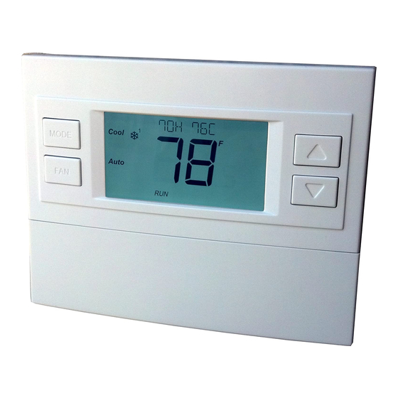
Page 10: Main Thermostat Screen
Operation Guide Model TBZ48A Battery Powered Z-Wave Thermostat Main Thermostat Screen Backlit Display Text Display Line Room Temperature Temperature Setting 72H 80C Heating/Cooling Warmer MODE Mode Selection Cooler Fan Mode Auto Selection Battery Compartment Flip down door 2xAA or 4xAA Alkaline Batteries... -
Page 11: Setting The System Mode: Off, Heat, Cool, Auto
Staging Indicators “1” = Stage 1 heating or cooling is ON “2” = Stage 2 heating or cooling is ON “3” = Stage 3 heating (Aux Heat) is ON For Heat Pump systems only: “Heat-E” = Emergency heat mode active Setting the System Mode: Off, Heat, Cool, Auto 72H 80C MODE... -
Page 12: Setting The Heating Or Cooling Temperature Setpoint
Setting the Heating or Cooling Temperature Setpoint 72H 80C MODE Press either Up or Down arrow button to go to the Auto Setpoint Change screen Setpoint Change screen Press the Up or Down arrow buttons to set the desired Setpoint being changed temperature setpoint Set to Heat... -
Page 13: Setting The Fan Mode
Setting the Fan Mode 72H 80C MODE Auto Press the FAN button to change the Fan mode Fan Modes: Auto: Fan automatically operated by the HVAC system. (normal setting) On: Manual Fan mode. Fan stays on until mode is changed back to Auto, independent of the heating or cooling system operation. -
Page 14: Menu Mode Screen
Thermostat Menu Mode The Thermostat has a menu of setup and information displays. Change to the Menu Mode by pressing and holding the FAN button for 5 seconds. The display will change to Menu Mode and you can scroll through the menu options with the Up/Down arrow buttons. - Page 15 SETUP Menu User preference settings. DEG F/C Select the temperature display mode, Fahrenheit (F) or Celsius (C). BAKLITE Sets the time from last button press that the backlight will timeout and turn off. The backlight will turn OFF after the selected time expires. Range:10-30 seconds. Note: long backlight timeouts will reduce battery life.
-
Page 16: Thermostat Operation
CO Select the Changeover type (HP systems only), changeover with Heat or Cool See Installation Guide for more information on System setup and the Advanced Systems Menu Thermostat Operation Minimum Run Time (MRT) The thermostat has a Minimum Run Time after the start of any heating or cooling call. This minimum run time assures even heating and cooling cycles. -
Page 17: Z-Wave® Operation
Z-Wave network. If the TBZ48A is installed in a network while powered by 24VAC, it will be installed as an always-listening device and can act as a router node in the Z-Wave network. - Page 18 Press the UP button until ZWAVE is shown on the status line then press Select. REMOVE should be displayed. Press Select to remove from the network. The status display will show the progress as the TBZ48A has been removed from a network. Wait until SUCCESS or FAILED is shown on the status line.
- Page 19 FCC/IC INFORMATION TO USER This device complies with Part 15 of the FCC Rules. Operation is subject to the following two conditions: (1) This device may not cause harmful interference, and (2) This device must accept any interference received, including interference that may cause undesired operation.
Need help?
Do you have a question about the TBZ48A and is the answer not in the manual?
Questions and answers
I have changed the battery and the text line says “Battery” . Nothing else seems to be working. Am I doing something wrong or is my thermostat broken?