Table of Contents
Advertisement
Quick Links
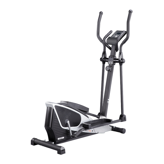
CLASSIC PRO
Elliptical Cross Trainer
ITEM NO.: 93790
OWNER'S MANUAL
IMPORTANT: Read all instructions carefully before using this product. Retain this
owner's manual for future reference.
The specifications of this product may vary from this photo and are subject to change without
prior notice.
2015, April
Advertisement
Table of Contents

Related Manuals for LifeGear CLASSIC PRO 93790


Summary of Contents for LifeGear CLASSIC PRO 93790
- Page 1 CLASSIC PRO Elliptical Cross Trainer ITEM NO.: 93790 OWNER’S MANUAL IMPORTANT: Read all instructions carefully before using this product. Retain this owner’s manual for future reference. The specifications of this product may vary from this photo and are subject to change without prior notice.
-
Page 2: Table Of Contents
TABLE OF CONTENTS WARRANTY ------------------------------------------------------------------------------- 2 IMPORTANT SAFETY INSTRUCTIONS ------------------------------------------- 3 PARTS LIST ------------------------------------------------------------------------------- 4 HARDWARE AND TOOLS PACK ---------------------------------------------------- 6 FRONT & REAR DECORATIVE COVERS PACK ------------------------------- 7 HANDRAIL ARM COVERS PACK --------------------------------------------------- 7 OVERVIEW DRAWING ----------------------------------------------------------------- 8 ASSEMBLY INSTRUCTIONS --------------------------------------------------------- 9 HOW TO MOVE THE ELLIPTICAL TRAINER ------------------------------------ 31 OPERATING THE COMPUTER ------------------------------------------------------ 32 ADJUSTMENTS -------------------------------------------------------------------------- 33... -
Page 3: Warranty
ONE YEAR LIMITED WARRANTY LifeGear Inc. warrants to the original purchaser that this product is free from defects in material and workmanship when used for the purpose intended, under the conditions that it has been installed and operated in accordance with LifeGear's Owner's Manual. LifeGear's obligation under this warranty is limited to replacing or repairing free of charge, any parts which may prove to be defective under normal home use. -
Page 4: Important Safety Instructions
IMPORTANT SAFETY INSTRUCTIONS Basic precautions should always be followed, including the following important safety instructions when using this equipment. Read all instructions before using this equipment. Read all instructions and follow it carefully before using this equipment. Make sure the equipment is properly assembled and tightened before use. -
Page 5: Parts List
PARTS LIST Description Qty No. Description 001 Carriage Bolt M8x75 4 024 Handlebar Ø28 Hexagon Socket Pan Head Cap 002 Rear Stabilizer Ø60x1.5tx480 1 025 Bolt M8x25 Handlebar Foam Grip 003 Rear Stabilizer End Cap Ø60 2 026 Ø28x5tx480 004 Curve Washer Ø8.5xØ18x1.5t 12 027 Hand Pulse Sensor 005 Spring Washer Ø8.5xØ14x2.0t 8 028 Handlebar End Cap Ø33xØ24... - Page 6 PARTS LIST Description Qty No. Description 044L Left Foot Pedal 1 061 Belt (PJ370) 044R Right Foot Pedal 1 062 Idler Arm 045 Hexagon Bolt M8x50 2 063 Bearing 6000Z Cross Recessed Pan Head Bolt 046L Left Foot Bar 1 064 M5x12 046R Right Foot Bar 1 065 Washer Ø25x3.0t...
-
Page 7: Hardware And Tools Pack
HARDWARE AND TOOLS PACK (47L) Left Bolt 1/2" 1 PC (48) Wave Washer Ø16.5xØ23 1 PC (51) Spring Washer Ø13xØ20x3.0t 1 PC (52L) Left Nylon Nut 1/2" 1 PC (47R) Right Bolt 1/2" 1 PC (48) Wave Washer Ø16.5xØ23 1 PC (51) Spring Washer Ø13xØ20x3.0t 1 PC... -
Page 8: Front & Rear Decorative Covers Pack
S6 Allen Wrench with S8 Allen Wrench Phillips Screwdriver 1 PC 1 PC Multi Hex Tool Multi Hex Too 1 PC 1 PC FRONT & REAR DECORATIVE COVERS PACK (16) M4.8x16 Cross Recessed Pan Head Tapping Screw 2 PCS (15A) Front Decorative Cover for Front Post 1 PC (15B) Rear Decorative Cover for Front Post 1 PC... -
Page 9: Overview Drawing
OVERVIEW DRAWING 4 33 35 B 35 A 15 A 15 B 4 33 35 A... -
Page 10: Assembly Instructions
ASSEMBLY INSTRUCTIONS STEP 1 Position the Front Stabilizer (7) in front of the Main Frame (69) and align bolt holes. Attach the Front Stabilizer (7) onto the front curve of the Main Frame (69) with two M8x75 Carriage Bolts (1), two Ø8.5xØ18x1.5t Curve Washers (4), two Ø8.5xØ14x2.0t Spring Washers (5), and two M8 Cap Nuts (6). - Page 11 STEP 2 Position the Rear Stabilizer (2) behind the Main Frame (69) and align bolt holes. Attach the Rear Stabilizer (2) onto the rear curve of the Main Frame (69) with two M8x75 Carriage Bolts (1), two Ø8.5xØ18x1.5t Curve Washers (4), two Ø8.5xØ14x2.0t Spring Washers (5), and two M8 Cap Nuts (6).
- Page 12 STEP 3 Remove two Ø8.5xØ16x1.5t Washers (10), four Ø8.5xØ18x1.5t Curve Washers (4), and six M8x20 Hexagon Socket Pan Head Cap Bolts (9) from the Main Frame (69). Remove bolts with the S6 Allen Wrench with Phillips Screwdriver provided.
- Page 13 STEP 4 It is recommended to have a second person assist with this step. One person should hold the Front Post (11) in place while the other person to connect the wires. Connect the Sensor Wire (74) from the Main Frame (69) to the Extension Sensor Wire (75) from the Front Post (11).
- Page 14 STEP 5 Insert the Front Post (11) onto the tube of the Main Frame (69) and secure with two Ø8.5xØ16x1.5t Washers (10), four Ø8.5xØ18x1.5t Curve Washers (4), and six M8x20 Hexagon Socket Pan Head Cap Bolts (9) that were removed. Tighten bolts with the S6 Allen Wrench with Phillips Screwdriver provided.
- Page 15 15 A 15 B STEP 6 Attach the Front Decorative Cover for Front Post (15A) and Rear Decorative Cover for Front Post (15B) onto the Front Post (11) with two ST4.8x16 Cross Recessed Pan Head Tapping Screws (16). Tighten screws with the S6 Allen Wrench with Phillips Screwdriver provided. Front &...
- Page 16 STEP 7 Remove two M10x45 Hexagon Bolts (43), two Ø10.5xØ20 Washers (41), and two M10 Nylon Nuts (42) from the Left Foot Bar (46L). Remove bolts and nylon nuts with two Multi Hex Tools provided. Use the same procedure to remove the bolts, washers, and nylon nuts on the Right Foot Bar (46R).
- Page 17 STEP 8 Attach the Left Foot Pedal (44L) onto the Left Foot Bar (46L) with two M10x45 Hexagon Bolts (43), two Ø10.5xØ20 Washers (41), and two M10 Nylon Nuts (42) that were removed from the Left Foot Bar (46L). Tighten the nylon nuts with the Multi Hex Tool provided. Use the same procedure to attach the Right Foot Pedal (44R) onto the Right Foot Bar (46R).
- Page 18 STEP 9 Remove two M4.8x20 Screws (37) from the Left Foot Bar (46L). Remove screws with the S6 Allen Wrench with Phillips Screwdriver provided. Attach the Front Left Foot Bar Cover (38L) and Front Right Foot Bar Cover (38R) onto the front end of the Left Foot Bar (46L) with two M4.8x20 Screws (37) that were removed from the Left Foot Bar (46L).
- Page 19 STEP 10 Remove one M8x20 Hexagon Socket Pan Head Cap Bolt (21), one Ø8.5xØ14x2.0t Spring Washer (5), one Ø8.5xØ29x3.0t Big Washer (20), and one Ø19.5xØ29x3.0t Washer (19) from the right horizontal axis of the Front Post (11). Remove bolt with the S6 Allen Wrench with Phillips Screwdriver provided.
- Page 20 STEP 11 Attach the Left Handrail Arm (36L) onto the left horizontal axis of the Front Post (11) with one M8x20 Hexagon Socket Pan Head Cap Bolt (21), one Ø8.5xØ14x2.0t Spring Washer (5), one Ø8.5xØ29x3.0t Big Washer (20), and one Ø19.5xØ29x3.0t Washer (19) that were removed from the left horizontal axis of the Front Post (11).
- Page 21 STEP 12 Attach the Right Handrail Arm (36R) onto the right horizontal axis of the Front Post (11) with one M8x20 Hexagon Socket Pan Head Cap Bolt (21), one Ø8.5xØ14x2.0t Spring Washer (5), one Ø8.5xØ29x3.0t Big Washer (20), and one Ø19.5xØ29x3.0t Washer (19) that were removed from the right horizontal axis of the Front Post (11).
- Page 22 STEP 13 Attach the left Foot Bar Bracket (50) to the left Crank (66) with one 1/2” Left Bolt (47L), one Ø16.5xØ23 Wave Washer (48), one Ø13xØ20x3.0t Spring Washer (51), and one 1/2” Left Nylon Nut (52L). Tighten bolt and nylon nut with the S8 Allen Wrench and Multi Hex Tool provided.
- Page 23 STEP 14 Attach the right Foot Bar Bracket (50) to the right Crank (66) with one 1/2” Right Bolt (47R), one Ø16.5xØ23 Wave Washer (48), one Ø13xØ20x3.0t Spring Washer (51), and one 1/2” Right Nylon Nut (52R). Tighten bolt and nylon nut with the S8 Allen Wrench and Multi Hex Tool provided.
- Page 24 10 5 STEP 15 Remove two M8x25 Hexagon Socket Pan Head Cap Bolts (25), two Ø8.5xØ14x2.0t Spring Washers (5), and two Ø8.5xØ16x1.5t Washers (10) from the Front Post (11). Remove bolts with the S6 Allen Wrench with Phillips Screwdriver provided.
- Page 25 10 5 STEP 16 Insert the Hand Pulse Sensor Wires (76) from the Handlebar (24) into the hole on the Front Post (11) and then pull them out from the top end of the Front Post (11). Attach the Handlebar (24) onto the Front Post (11) with two M8x25 Hexagon Socket Pan Head Cap Bolts (25), two Ø8.5xØ14x2.0t Spring Washers (5), and two Ø8.5xØ16x1.5t Washers (10) that were removed from the Front Post (11).
- Page 26 STEP 17 Remove two M8x40 Hexagon Bolts (32), two Ø8.5xØ18x1.5t Curve Washers (4), and two M8 Hexagon Nylon Nuts (33) from Left Handrail (31L). Remove bolts and nylon nuts with two Multi Hex Tools provided. Use the same procedure to remove the bolts, curve washers, and nylon nuts on the Right Handrail (31R).
- Page 27 STEP 18 Insert both Left and Right Handrails (31L, 31R) into the top ends of both Left and Right Handrail Arms (36L, 36R).
- Page 28 4 33 STEP 19 Secure both Left and Right Handrails (31L, 31R) into the top ends of both Left and Right Handrail Arms (36L, 36R) with four M8x40 Hexagon Bolts (32), four Ø8.5xØ18x1.5t Curve Washers (4), and four M8 Hexagon Nylon Nuts (33) that were removed from Left and Right Handrails (31L, 31R).
- Page 29 35 B 35 A 35 A STEP 20 Attach the Handrail Arm Cover-A (35A) and Handrail Arm Cover-B (35B) onto the Left Handrail Arm (36L) with four ST4.8x16 Cross Recessed Pan Head Tapping Screws (16). Tighten screws with the S6 Allen Wrench with Phillips Screwdriver provided. Attach the other Handrail Arm Cover-A (35A) and Handrail Arm Cover-B (35B) onto the Right Handrail Arm (36R) with four ST4.8x16 Cross Recessed Pan Head Tapping Screws (16).
- Page 30 STEP 21 Remove two M6x15 Cross Recessed Pan Head Bolts (23) from the Computer (22). Remove bolts with the S6 Allen Wrench with Phillips Screwdriver provided.
- Page 31 STEP 22 It is recommended to have a second person assist with this step. One person should hold the Computer (22) in place while the other person to connect the wires. Connect the Extension Sensor Wire (75) and Hand Pulse Sensor Wires (76) to the wires that come from the Computer (22).
-
Page 32: How To Move The Elliptical Trainer
HOW TO MOVE THE ELLIPTICAL TRAINER Left & Right Handrails Transport Wheel This elliptical trainer has a pair of Transport Wheels built into the front stabilizer and can be carefully tilted onto its Transport Wheels for easy moving and storage. Stand in front of the unit and grasp the Left and Right Handrails with both hands, then push or pull both handrails to make them parallel. -
Page 33: Operating The Computer
OPERATING THE COMPUTER USING YOUR COMPUTER The computer can be activated by pressing the MODE button or by pedaling. If you leave the equipment idle for 4-5 minutes, the power will turn off automatically. BUTTON FUNCTIONS: Press the MODE button to select the functions of the computer. Press and hold the MODE button for 3 seconds to reset all data values to zero except the ODO (ODOMETER) data values. -
Page 34: Adjustments
ADJUSTMENTS Adjusting the Tension Control Knob To increase the tension, turn the tension control knob in a clockwise direction. To decrease the tension, turn the tension control knob in a counterclockwise direction. Tension Control Knob Adjusting the Adjustable Leveler Turn the adjustable leveler on the rear stabilizer end cap as needed to level the elliptical trainer. -
Page 35: Maintenance
MAINTENANCE Cleaning The elliptical trainer can be cleaned with a soft clean damp cloth. Do not use abrasives or solvents on plastic parts. Please wipe your perspiration off the elliptical trainer after each use. Be careful not to get excessive moisture on the computer display panel as this might cause an electrical hazard or electronics to fail. -
Page 36: Warm Up And Cool Down Routine
WARM UP AND COOL DOWN ROUTINE The WARM-UP is an important part of any workout. The purpose of warming up is to prepare your body for exercise and to minimize injuries. Warm up for two to five minutes before aerobic exercising. It should begin every session to prepare your body for more strenuous exercise by heating up and stretching your muscles, increasing your circulation and pulse rate, and delivering more oxygen to your muscles. - Page 37 QUADRICEPS STRETCH With one hand against a wall for balance, reach behind you and pull your right foot up. Bring your heel as close to your buttocks as possible. Hold for 15 counts and repeat with left foot. INNER THIGH STRETCH Sit with the soles of your feet together and your knees pointing outward.
Need help?
Do you have a question about the CLASSIC PRO 93790 and is the answer not in the manual?
Questions and answers