Table of Contents
Advertisement
Quick Links
Advertisement
Table of Contents

Related Manuals for LifeGear 93260


Summary of Contents for LifeGear 93260
-
Page 1: Elliptical Trainer
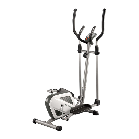
CLASSIC ELLIPTICAL TRAINER ITEM NO.: 93260 OWNER’S MANUAL IMPORTANT: Read all instructions carefully before using this product. Retain this owner’s manual for future reference. The specifications of this product may vary from this photo, subject to change without notice. 2011, Oct. -
Page 2: Table Of Contents
WARM UP AND COOL DOWN ROUTINE ----------------------------------------- 18 ONE YEAR LIMITED WARRANTY LifeGear Inc. warrants to the original purchaser that this product is free from defects in material and workmanship when used for the purpose intended, under the conditions that it has been installed and operated in accordance with LifeGear's Owner's Manual. -
Page 3: Safety Instructions
SAFETY INSTRUCTIONS Basic precautions should always be followed, including the following safety instructions when using this equipment: Read all instructions before using this equipment. Read all the instructions in this manual and do warm up exercises before using this equipment. Before exercise, in order to avoid injuring the muscle, warm-up exercise of every position of the body is necessary. -
Page 4: Parts List
PARTS LIST Description Qty No. Description 001 Main Frame Ø50x2 1 027 Nylon Nut M6 002L Left Foot Bar 40x25x1.5 1 028 Washer Ø6 002R Right Foot Bar 40x25x1.5 1 029 Bolt M6x40 003L Left Handrail Arm Ø32x1.5 1 030 Tension Cable L=1600 003R Right Handrail Arm Ø32x1.5 1 031 Bolt Cap S13 004L Left Handrail Ø32x1.5... - Page 5 PARTS LIST Description Qty No. Description 055 Screw ST2.9x12 8 075 Bearing Nut II 7/8” 056 Computer JVT 29104 1 076 Washer Ø34.5xØ23x2.5 057 Bolt M5x12 4 077 Hexagon Nut 7/8” 058 Hand Pulse Sensor with Wire 2 078 Belt Pulley with Crank Ø240 L=750 059 Handrail Foam Grip 2 079 Powder Metal Bushing Ø18xØ8x5...
-
Page 6: Hardware Packing List
HARDWARE PACKING LIST (16R) Bolt for right U Shape (16L) Bolt for left U Shape Bracket Ø16x88.5xL23 1 PC Bracket Ø16x88.5xL23 1 PC (17R) Right Nylon Nut 1/2” 1 PC (17L) Left Nylon Nut 1/2” 1 PC (18) Wave Washer (18) Wave Washer Ø28xØ17x0.3 1 PC... -
Page 7: Tools
TOOLS Allen Wrench S6 Allen Wrench S8 1 PC 1 PC Multi Hex Tool with Phillips Screwdriver Multi Hex Tool S10, S13, S14, S15 S10, S13, S17, S19 1 PC 1 PC... -
Page 8: Overview Drawing
OVERVIEW DRAWING... -
Page 9: Assembly Instructions
ASSEMBLY INSTRUCTIONS Tool: Multi Hex Tool S10, S13, S17, S19 1. Front and Rear Stabilizers Installation Position the Front Stabilizer (10) in front of Main Frame (1) and align bolt holes. Attach the Front Stabilizer (10) onto the front curve of the Main Frame (1) with two M10x57 Bolts (12), two Ø10 Big Curve Washers (14), and two M10 Cap Nuts (15). - Page 10 Tool: Allen Wrench S6 Multi Hex Tool with Phillips Screwdriver S10, S13, S14, S15 2. Front Post and Tension Control Knob Installation Remove six M8x16 Bolts (41), six Ø8 Spring Washers (60), and six Ø20xØ8 Curve Washers (42) from the Main Frame (1). Remove bolts and washers with the S6 Allen Wrench provided.
- Page 11 Tool: Multi Hex Tool with Phillips Screwdriver S10, S13, S14, S15 Allen Wrench S8 17L(R) (37) 16L(R) Multi Hex Tool S10, S13, S17, S19 3. Left/Right Handrail Arms, Left/Right Foot Bars, Left/Right Foot Pedals, and Foot Bar Covers-A/B Installation Remove two M10x18 Bolts (43), two Ø18xØ10x2 Spring Washers (44), two Ø20xØ10x2 Big Washers (92), and two Ø28x5 Washers (45) from the left and right horizontal axes of the Front Post (5).
-
Page 12: Washer Ø28X5
Attach the Foot Bar Covers-A/B (33L, 33R) onto the Left Foot Bar (2L) with two ST4.2x20 Screws (69). Tighten screws with the Multi Hex Tool with Phillips Screwdriver provided. Repeat above step to attach the Right Handrail Arm (3R) onto the right horizontal axis of the Front Post (5) and right U Shape Bracket (23) to the right Crank (78). - Page 13 Tool: Multi Hex Tool with Phillips Screwdriver S10, S13, S14, S15 4. Left and Right Handrails Installation Attach the Left/Right Handrails (4L, 4R) onto the Left/Right Handrail Arms (3L, 3R) with four M6x35 Bolts (47), four Ø6 Curve Washers (48), and four M6 Cap Nuts (50). Tighten cap nuts with the Multi Hex Tool with Phillips Screwdriver provided.
- Page 14 Tool: Multi Hex Tool with Phillips Screwdriver S10, S13, S14, S15 5. Left and Right Handrail Arm Covers-A and B Installation Attach the Left Handrail Arm Cover-A (52L) and Left Handrail Arm Cover-B (53L) onto the Left Handrail Arm (3L) with four ST2.9x12 Screws (55). Tighten screws with the Multi Hex Tool with Phillips Screwdriver provided.
- Page 15 Tool: Multi Hex Tool with Phillips Screwdriver S10, S13, S14, S15 Allen Wrench S6 6. Handlebar and Computer Installation Remove four M5x12 Bolts (57) from the back of the Computer (56). Remove bolts with the Multi Hex Tool with Phillips Screwdriver provided. Remove two M8x16 Bolts (41) and two Ø16xØ8x1.5 Curve Washers (93) from the Front Post (5).
-
Page 16: Operating The Computer
OPERATING THE COMPUTER COMPUTER FUNTIONS: AUTO ON /OFF: When you start to exercise or press MODE button on the computer, the computer will turn on. If you leave the equipment for 4 minutes, the power will turn off automatically. SCAN: Press the MODE button until the arrow points to SCAN, the computer will automatically scans each function in sequence with change every 5 seconds. -
Page 17: Adjustments
ADJUSTMENTS Adjusting the Tension Control Knob To increase the load, turn the tension control knob in a clockwise direction. To decrease the load, turn the tension control knob in a counterclockwise direction. Tension Control Knob Adjusting the Rear Stabilizer End Cap Turn the rear stabilizer end cap on the rear stabilizer as needed to level the elliptical trainer. -
Page 18: Maintenance
MAINTENANCE Cleaning The elliptical trainer can be cleaned with a soft cloth and mild detergent. Do not use abrasives or solvents on plastic parts. Please wipe your perspiration off the elliptical trainer after each use. Be careful not get excessive moisture on the computer display panel as this might cause an electrical hazard or electronics to fail. -
Page 19: Warm Up And Cool Down Routine
WARM UP AND COOL DOWN ROUTINE A good exercise program consists of a warm-up, aerobic exercise, and a cool down. Do the entire program at least two to three times a week, resting for a day between workouts. After several months you can increase your workouts to four or five times per week. AEROBIC EXERCISE is any sustained activity that sends oxygen to your muscles via your heart and lungs. - Page 20 SIDE STRETCHES Open your arms to the side and lift them until they are over your head. Reach your right arm as far toward the ceiling as you can for one count. Repeat this action with your left arm. QUADRICEPS STRETCH With one hand against a wall for balance, reach behind you and pull your right foot up.
- Page 21 TOE TOUCHES Slowly bend forward from your waist, letting your back and shoulders relax as you stretch toward your toes. Reach as far as you can and hold for 15 counts. HAMSTRING STRETCHES Extend your right leg. Rest the sole of your left foot against your right inner thigh.
Need help?
Do you have a question about the 93260 and is the answer not in the manual?
Questions and answers