Table of Contents
Advertisement
Quick Links
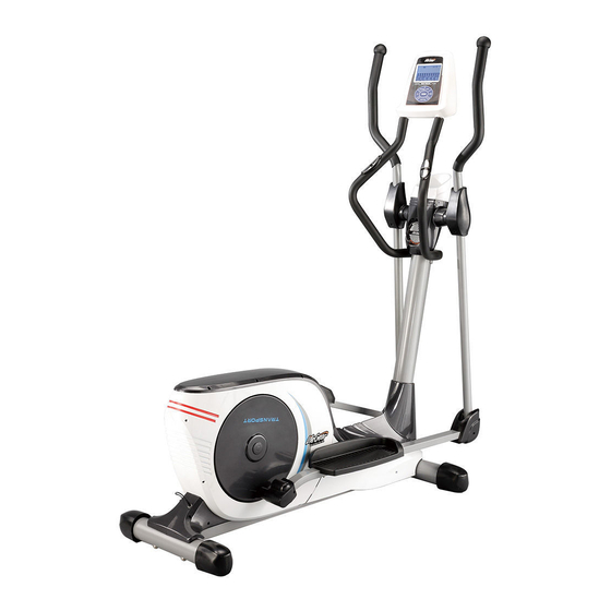
TRANSPORT PC
PRO MAGNETIC ELLIPTICAL
TRAINER
ITEM NO.: 93690
OWNER'S MANUAL
IMPORTANT: Read all instructions carefully before using this product. Retain this
owner's manual for future reference.
The specifications of this product may vary from this photo, subject to change without notice.
2011, June
Advertisement
Table of Contents

Related Manuals for LifeGear 93690


Summary of Contents for LifeGear 93690
- Page 1 TRANSPORT PC PRO MAGNETIC ELLIPTICAL TRAINER ITEM NO.: 93690 OWNER’S MANUAL IMPORTANT: Read all instructions carefully before using this product. Retain this owner’s manual for future reference. The specifications of this product may vary from this photo, subject to change without notice.
-
Page 2: Table Of Contents
WARM UP AND COOL DOWN ROUTINE ----------------------------------------- 23 ONE YEAR LIMITED WARRANTY LifeGear Inc. warrants to the original purchaser that this product is free from defects in material and workmanship when used for the purpose intended, under the conditions that it has been installed and operated in accordance with LifeGear's Owner's Manual. -
Page 3: Safety Instructions
SAFETY INSTRUCTIONS Basic precautions should always be followed, including the following safety instructions when using this equipment: Read all instructions before using this equipment. Read all the instructions in this manual and do warm up exercises before using this equipment. Before exercise, in order to avoid injuring the muscle, warm-up exercise of every position of the body is necessary. -
Page 4: Parts List
PARTS LIST Description Qty No. Description 001 Handrail End Cap Ø32x1.5t 2 024 Curve Washer Ø16xØ8x1.5t 002L Left Handrail Ø32x1.5t 1 025 Bolt M8x15mm 002R Right Handrail Ø32x1.5t 1 026 Nut M6 003L Left Handrail Arm 1 027 Phillips Self Tapping Screw ST4.2x20mm 003R Right Handrail Arm 1 028 Left Handrail Arm Cover-A... - Page 5 PARTS LIST Description Qty No. Description 048L Front Left Stabilizer End Cap 1 071 Screw ST4.2x25mm 048R Front Right Stabilizer End Cap 1 072 Sensor Wire I (1600L) 049 Front Stabilizer Ø76 1 073 Belt Pulley Shaft 050 Bolt M8x90mm 4 074 Plastic Disc Cap 051 Transport Wheel Ø45x19 2 075L Left Shroud...
-
Page 6: Hardware Packing List
HARDWARE PACKING LIST (8) Screw ST2.9x16mm (9) Screw ST4.2x20mm (10) Nylon Nut M6 20 PCS 4 PCS 10 PCS (11) Curve Washer Ø6 (12) Carriage Bolt M6x35mm (27) Phillips Self Tapping 4 PCS 4 PCS Screw ST4.2x20mm 10 PCS (40) Big Washer Ø6 (47) Hexagon Head Bolt (50) Bolt M8x90mm 6 PCS... -
Page 7: Overview Drawing
OVERVIEW DRAWING... -
Page 8: Assembly Instructions
ASSEMBLY INSTRUCTIONS Tool: Allen Wrench S6 1. Front and Rear Stabilizers Installation Position the Front Stabilizer (49) in front of Main Frame (60) and align bolt holes. Attach the Front Stabilizer (49) onto the front curve of the Main Frame (60) with two M8x90mm Bolts (50) and two Ø8xØ20x1.5t Big Curve Washers (54). - Page 9 24 25 Tool: Allen Wrench S6 2. Front Post and Front Post Cover Installation Remove six Ø16xØ8x1.5t Curve Washers (24) and six M8x15mm Bolts (25) from the Main Frame (60). Remove bolts and curve washers with an Allen Wrench provided. Slide the Front Post Cover (56) up to the Front Post (32).
- Page 10 Tool: 15 14 13 Multi Hex Tool with Phillips Screwdriver S10, S13, S14, S15 Allen Wrench S6 3. Left/Right Handrail Arms, Left/Right Foot Bars, and Foot Bar Bracket Covers Installation Remove two M8x20mm Bolts (13), two Ø8 Spring Washers (14), and two Ø38x3 Washers (15) from the left and right horizontal axes of the Front Post (32).
- Page 11 Tool: 45L 45R Multi Hex Tool with Phillips Screwdriver S10, S13, S14, S15 4. Left/Right Foot Pedals, and Front Left/Right Foot Bar Covers Installation Attach the Left Foot Pedal (88L) onto the Left Foot Bar (53L) with three M6 Nylon Nuts (10), three Ø6 Big Washers (40), and three M6x40 Hexagon Head Bolts (47).
-
Page 12: Phillips Self Tapping Screw
10 11 Tool: 10 11 Multi Hex Tool with Phillips Screwdriver S10, S13, S14, S15 5. Left/Right Handrails and Left/Right Handrail Arm Covers-A/B Installation Attach the Left/Right Handrails (2L, 2R) onto the Left/Right Handrail Arms (3L, 3R) with four M6 Nylon Nuts (10), four Ø6 Curve Washers (11), and four M6x35mm Carriage Bolts (12). Tighten bolts and nylon nuts with a Multi Hex Tool with Phillips Screwdriver provided. - Page 13 Tool: Multi Hex Tool with Phillips Screwdriver S10, S13, S14, S15 6. Top and Rear/Front Decorative Covers for Front Post Installation Attach the Top and Rear/Front Decorative Covers for Front Post (5, 6, 7) onto the Front Post (32) with six ST2.9x16mm Screws (8) and two ST4.2x20mm Screws (9). Tighten screws with a Multi Hex Tool with Phillips Screwdriver provided.
-
Page 14: Computer Extension Wire I
Tool: Allen Wrench S6 Multi Hex Tool with Phillips Screwdriver S10, S13, S14, S15 7. Handlebar and Computer Installation Remove two Ø16xØ8x1.5t Curve Washers (24) and two M8x20mm Bolts (93) from the Front Post (32). Remove bolts and curve washers with an Allen Wrench provided. Connect the Computer Extension Wire I (30) from the Front Post (32) to the Computer Extension Wire II (89) from the Handlebar (23). -
Page 15: Power Supply Wire
8. AC Adapter Installation Plug one end of the AC Adapter (92) into the power jack of the Power Supply Wire (90) on the back of the Left Shroud (75L). Before plugging in, make sure to check carefully the specifications on the Adapter. Plug the other end of the AC Adapter (92) into the electrical wall outlet. -
Page 16: Operating The Computer
OPERATING THE COMPUTER BUTTON FUNCTIONS: START/STOP: Press the START/STOP button to start or stop training. ENTER: Press the ENTER button to choose the functions from PROGRAMS, GENDER, TIME, HEIGHT, WEIGHT, DISTANCE, CALORIES, TARGET HEART RATE, AGE, and 10 intervals. The chosen function shall flash. Please note that not all the functions can be selected in every program according to the types of each program. - Page 17 Your ratings for Pulse Recovery are as follows: F1.0 = Excellent F4.0 = Below Average F2.0 = Good F5.0 = Not Good F3.0 = Fair F6.0 = Poor About Display: START: Indicates the program selected has started. STOP: Indicates the program selected has stopped. User is free to change the programs and the value of functions applied.
- Page 18 Operating Ranges Values Range (Count up) Count down Preset Increment (Decrement) PROGRAM 1 ~ 13 13 ~ 1 LEVEL 1 ~ 16 16 ~ 1 GENDER Male, Female Male TIME 0:00 ~ 99:59 99:00 ~ 1:00 0:00 1:00 HEIGHT (cm) 100 ~ 250 250 ~ 100 WEIGHT (kg)
- Page 19 Program 3 (Valley) Program 4 (Fat Burn) Program 5 (Ramp) Program 6 (Mountain) Program 7 (Random) Program 8 (Body Fat) Program 9 (Target H.R.) Program 10 (60% H.R.C.) Program 11 (75% H.R.C.) Program 12 (85% H.R.C.) Program 13 (User Setting)
- Page 20 Body Types: There are 9 body types divided according to the FAT% calculated. TYPE 1 (5%-10%) Extremely athletic TYPE 2 (>10%-15%) Ideal sportsman TYPE 3 (>15%-20%) Very slender TYPE 4 (>20%-25%) Sportsman TYPE 5 (>25%-30%) Ideal health TYPE 6 (>30%-35%) Slender overweight TYPE 7 (>35%-40%) Very overweight TYPE 8...
- Page 21 exercise again. Pre-set Programs: PROGRAM 2 to PROGRAM 7 are the pre-set programs. Press the ENTER button to select TIME, DISTANCE, CALORIES, or AGE for target pre-setting. Then press the UP or DOWN button to adjust the values. User may exercise with different level of loading in different intervals as the profiles show.
-
Page 22: Adjustment
Heart Rate Control Programs: Program 10 to Program 12 are the Heart Rate Control Programs. In Program 10 to Program 12, press the ENTER button to select TIME, DISTANCE, CALORIES, and AGE. Then press the UP or DOWN button to adjust the values. Users may exercise in a period of time, a certain distance, or a certain calories want to burn with 60% Max Heart Rate in Program10, 75% Max Heart Rate in Program 11, and 85% Max Heart Rate in Program 12. -
Page 23: Maintenance
MAINTENANCE Cleaning The elliptical trainer can be cleaned with a soft cloth and mild detergent. Do not use abrasives or solvents on plastic parts. Please wipe your perspiration off the elliptical trainer after each use. Be careful not get excessive moisture on the computer display panel as this might cause an electrical hazard or electronics to fail. -
Page 24: Warm Up And Cool Down Routine
WARM UP AND COOL DOWN ROUTINE A good exercise program consists of a warm-up, aerobic exercise, and a cool down. Do the entire program at least two to three times a week, resting for a day between workouts. After several months you can increase your workouts to four or five times per week. AEROBIC EXERCISE is any sustained activity that sends oxygen to your muscles via your heart and lungs. - Page 25 SIDE STRETCHES Open your arms to the side and lift them until they are over your head. Reach your right arm as far toward the ceiling as you can for one count. Repeat this action with your left arm. QUADRICEPS STRETCH With one hand against a wall for balance, reach behind you and pull your right foot up.
- Page 26 TOE TOUCHES Slowly bend forward from your waist, letting your back and shoulders relax as you stretch toward your toes. Reach as far as you can and hold for 15 counts. HAMSTRING STRETCHES Extend your right leg. Rest the sole of your left foot against your right inner thigh.
Need help?
Do you have a question about the 93690 and is the answer not in the manual?
Questions and answers