
Related Manuals for Alloy POEGE8T


Summary of Contents for Alloy POEGE8T
-
Page 1: User Manual
POEGE8T User Manual Gigabit Ethernet PoE+ Unmanaged Switch POEGE8T User Manual Version 1.0.0.2 – Oct 2012 Alloy Computer Products Pty Ltd Copyright ©2012... -
Page 2: Table Of Contents
3.3 Rack Installation ................7 ..........9 4. Powering on the Switch ............9 5. LED Description ........... 10 6. Network Connection ..........11 7. Technical Specifications .......... 12 Appendix A. RJ-45 Connections Alloy Computer Products Pty Ltd Copyright ©2012... -
Page 3: Compliances And Safety Statements
- Surge immunity test according to IEC 61000-4-5:2005 - Immunity to conducted disturbances, Induced by radio-frequency fields:IEC 61000-4-6:2008 - Power frequency magnetic field immunity test according to IEC 61000-4-8:2009 - Voltage dips, short interruptions and voltage variations immunity test Alloy Computer Products Pty Ltd Copyright ©2012... - Page 4 This unit operates under SELV (Safety Extra Low Voltage) conditions according to IEC 60950. The conditions are only maintained if the equipment to which it is connected also operates under SELV conditions. Alloy Computer Products Pty Ltd Copyright ©2012...
- Page 5 Please follow the instructions in the user manual/quick install guide carefully to connect the device to your PC or other electronic product. Any invalid connection may cause a power or fire risk. Do not place this device on an unstable surface or support. Alloy Computer Products Pty Ltd Copyright ©2012...
-
Page 6: Introduction
PD PoE devices, such as IP Phones, Wireless Access Points and IP Video Cameras. All ports support up to 30W of power, with the switch supporting 16W per port at full load. The POEGE8T supports up to 130W in total. -
Page 7: Installation
Fig. 1 Desktop installation 3.3 Rack Installation The POEGE8T is a rack mountable switch and can be installed in an EIA-19 based equipment rack. First install the provided rack mount brackets onto each side of the switch using the screws provided. Using the screws provided with your rack mount the switch into your equipment rack. - Page 8 POEGE8T User Manual Fig. 2 Rack Mount kit installation Fig. 3 Mounting the switch Alloy Computer Products Pty Ltd Copyright ©2012...
-
Page 9: Powering On The Switch
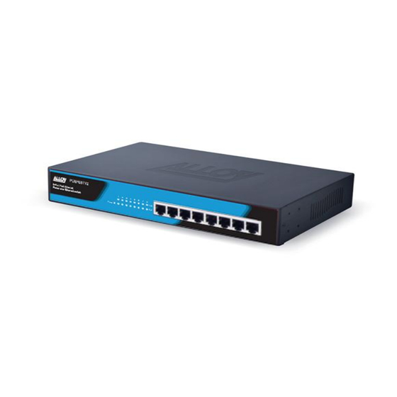
A valid link is established LINK Blink Traffic is present on port No link established PD PoE device has successfully connected to the port. No POE device connected Fig. 5 Front panel of switch Alloy Computer Products Pty Ltd Copyright ©2012... -
Page 10: Network Connection
Make sure each twisted pair cable does not exceed 100 meters (328 ft) in length. 3. As each connection is made, the relevant port LED (on the switch) corresponding to each port will turn on green to indicate that the connection is valid. Alloy Computer Products Pty Ltd Copyright ©2012... -
Page 11: Technical Specifications
280 x 179 x 44 (mm) Dimensions (W × D × H) Operating Temperature: 0°C - 40°C Storage Temperature: -40°C - 70°C Environment Operating Humidity: 10%~90% non-condensing Storage humidity: 5%~90% non-condensing Certification C-Tick, CE, FCC, RoHS Alloy Computer Products Pty Ltd Copyright ©2012... -
Page 12: Appendix A. Rj-45 Connections
However, if the unit powers off after running for a while, check for loose power connections, power losses or surges at the power outlet. If you still cannot isolate the problem, the internal power supply may be defective. Alloy Computer Products Pty Ltd Copyright ©2012... - Page 13 Below is a diagram of a typical straight through and cross-over cable connection: Fig. 5 Straight Through Cable connection Fig. 6 Cross-Over Cable connection Alloy Computer Products Pty Ltd Copyright ©2012...
Need help?
Do you have a question about the POEGE8T and is the answer not in the manual?
Questions and answers