Motorola MC70 User Manual
Enterprise digital assistant
Hide thumbs
Also See for MC70:
- Integration manual (208 pages) ,
- Application brief (4 pages) ,
- Brochure (12 pages)
Table of Contents
Advertisement
Quick Links
Download this manual
See also:
User Manual
Advertisement
Table of Contents
Troubleshooting

Related Manuals for Motorola MC70


Summary of Contents for Motorola MC70
- Page 1 MC70 Enterprise Digital Assistant User Guide...
- Page 3 MC70 Enterprise Digital Assistant User Guide 72E-71769-05 Rev. A April 2015...
- Page 4 MC70 User Guide © 2015 ZIH Corp No part of this publication may be reproduced or used in any form, or by any electrical or mechanical means, without permission in writing from Zebra. This includes electronic or mechanical means, such as photocopying, recording, or information storage and retrieval systems.
-
Page 5: Revision History
Revision History Changes to the original manual are listed below: Change Date Description -01 Rev A 1/2006 Initial release. -01 Rev B 8/2006 Add Revision History page. Chapter 2: Add vibrator feature information. Remove Green and Red Phone button remapping information. Not supported. Update cold boot procedure to remove step to calibrate screen after cold boot. - Page 6 MC70 User Guide...
-
Page 7: Table Of Contents
Table of Contents Revision History............................ iii About This Guide Introduction ............................xi Documentation Set Configurations............................xii Software Versions Chapter Descriptions ..........................xv Notational Conventions......................... xv Related Documents ..........................xvi Service Information..........................xvi Chapter 1: Getting Started Introduction ............................1-1 Unpacking ............................1-2 Accessories ............................ - Page 8 Turning Off the Radios ........................1-12 On Devices with Windows Mobile 5.0 AKU 1.0 ............... 1-12 On Devices with Windows Mobile 5.0 AKU 2.2 or higher ............1-12 Chapter 2: Using the MC70 Introduction ............................2-1 Status Icons ............................2-1 Speaker Icon ..........................
- Page 9 Table of Contents BTExplorer ............................3-5 Profiles Tab ............................ 3-5 Headset Audio Gateway Service ..................... 3-6 Virtual COM Port Tab ....................... 3-6 System Parameters ......................... 3-7 Chapter 4: Using Bluetooth Introduction ............................4-1 Adaptive Frequency Hopping ......................4-1 Security ..............................4-2 Turning the Bluetooth Radio Mode On and Off ...................
- Page 10 MC70 User Guide OBEX Object Push Service ..................... 4-25 Personal Area Networking Service ..................4-26 Serial Port Service ........................4-26 Security Tab ........................... 4-27 Discovery Tab ..........................4-27 Virtual COM Port Tab ........................4-28 Miscellaneous Tab ......................... 4-29 Chapter 5: Using the MC7004/94/95 Phone Introduction ............................
- Page 11 Charging the Spare Battery ......................6-8 Battery Charging Indicators ......................6-9 Charging Temperature ......................6-9 Four Slot Spare Battery Charger ......................6-9 MC70 Battery Shim Installation ...................... 6-9 Spare Battery Charging ......................... 6-10 Battery Charging Indicators ......................6-11 Charging Temperature ......................6-11 Magnetic Stripe Reader (MSR) ......................
- Page 12 MC70 User Guide Appendix A: Technical Specifications MC70 Technical Specifications ......................A-1 MC70 Accessory Specifications ......................A-5 Glossary Index...
-
Page 13: About This Guide
About This Guide Introduction This guide provides information about using the MC70 Enterprise Digital Assistant (EDA) and accessories. Screens and windows pictured in this guide are samples and can differ from actual screens. NOTE Documentation Set The documentation set for the MC70 provides information for specific user needs, and includes: •... -
Page 14: Configurations
MC70 User Guide Configurations This guide covers the following configurations: Data Operating Configuration Radios Display Memory Keypads Other Capture System MC7004 WPAN: Bluetooth 3.5” 64 MB RAM/ 1D laser Windows Numeric WWAN:GPRS QVGA 128 MB Flash scanner or Mobile 5.0... - Page 15 About This Guide xiii The second line lists the operating system version and the build number. The last part of the build number represents the AKU number. For example, Build 14929.2.2.1 indicates that the device is running AKU version 2.2.1. OEM Version To determine the OEM software version: >...
- Page 16 MC70 User Guide Fusion Software To determine the Fusion software version: icon > > Wireless Strength Wireless Status Versions Phone Software To determine the Phone software version: > > > > tab. Start Phone Menu Options Version Information...
-
Page 17: Chapter Descriptions
EDA. Notational Conventions The following conventions are used in this document: • “EDA” refers to the Zebra MC70 series of hand-held EDAs. • Italics are used to highlight the following: • Chapters and sections in this and related documents •... -
Page 18: Related Documents
• Sequential lists (e.g., those that describe step-by-step procedures) appear as numbered lists. Related Documents • MC70 Quick Start Guide, p/n 72-71770-xx • MC70 Microsoft Mobile 5.0 Regulatory Information, p/n 72-71767-xx • MC70 Integrator Guide, p/n 72E-71768-xx ® • Microsoft Applications for Mobile and CE 5.0 User Guide, p/n 72E-78456-xx... -
Page 19: Chapter 1 Getting Started
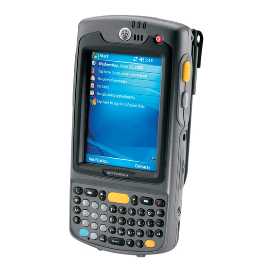
EDA for the first time. Charge Radio Power Scan/Decode Status LED Status LED Receiver Power Button Scan/Action Button Up/Down Button Touch Screen with Keypad Protective Overlay (Numeric Keypad Pictured) I/O Connector Microphone Handstrap Attachment MC70 Front View Figure 1-1... -
Page 20: Unpacking
1 - 2 MC70 User Guide Handstrap Battery Cover Handstrap Slot Battery Cover Latch Headset Jack Memory Card Slot Speaker Scan Window Action Button (Imager Model Shown) Scan/Action Button Tether Point Stylus MC70 Rear View Figure 1-2 Unpacking Carefully remove all protective material from the EDA and save the shipping container for later storage and shipping. -
Page 21: Accessories
VCD7000 Vehicle Cradle Installs in a vehicle and charges the EDA main battery and a spare battery. Provides serial data communication between an MC70 and an external device. Four Slot Spare Battery Charges up to four EDA spare batteries. Includes an adapter. -
Page 22: Getting Started
Installing the Main Battery Before using the EDA, install a lithium-ion battery. Depending upon the configuration, the MC70 may ship with a 1900 mAh, 3600 mAh or 3800 mAh battery. The 1900 mAh battery is shown. The extended capacity batteries requires a larger capacity battery cover. -
Page 23: Removing The Main Battery
Getting Started 1 - 5 Battery Cover Latch Battery Cover Inserting the Battery Cover Figure 1-4 Close the battery cover latches on either side of the battery cover. Insert the handstrap through the handstrap slot, then tighten and press down to secure. Handstrap Handstrap Slot Inserting the Handstrap... -
Page 24: Charging The Battery
40 hours. To charge batteries, use either a cable or one of the following cradles. For cradle setup and charging procedures refer to the MC70 Integrator Guide. • Single Slot USB/Serial Cradle •... -
Page 25: Charging Spare Batteries
Getting Started 1 - 7 Table 1-2 list the charge times for each available battery. Battery Charge Times Table 1-2 Battery Size Charge Time 1900 mAh Charges in less than four hours. 3600 mAh Charges in less than eight hours. 3800 mAh Charges in less than eight hours. -
Page 26: Charging Temperature
1 - 8 MC70 User Guide Charging Temperature Charge batteries in temperatures from 0°C to 40°C (32°F to 104°F). Note that at temperatures above 35°C, charging is intelligently controlled by the EDA and the charging accessory in order to ensure safe operation and optimize long-term battery life. -
Page 27: Adjusting The Handstrap
Make a call to verify connection. NOTE For detailed information about WWAN activation and settings, refer to the MC70 Integrator Guide. Adjusting the Handstrap The EDA handstrap is attached to the bottom of the battery cover. Adjust the handstrap to increase comfort when... -
Page 28: Removing The Screen Protector
Figure 1-10 Removing the Screen Protector A screen protector is applied to the MC70. Zebra recommends using this to minimize wear and tear. Screen protectors enhance the usability and durability of touch screen displays. To remove the screen protector, lift the corner using a thin plastic card, such as a credit card, then carefully lift it off the display. -
Page 29: Battery Management
Getting Started 1 - 11 Battery Management Observe the following battery saving tips: • Leave the EDA connected to AC power at all times when not in use. • Set the EDA to turn off after a short period of non-use. •... -
Page 30: Turning Off The Radios
1 - 12 MC70 User Guide Turning Off the Radios On Devices with Windows Mobile 5.0 AKU 1.0 NOTE To determine the operating system AKU version, see Configurations on page xii. Turning Off the WLAN Radio To turn off the WLAN radio, tap the icon and select . - Page 31 Getting Started 1 - 13 Opening Wireless Manager Figure 1-12 Select Wireless Manager Wireless Manager Window Figure 1-13 To enable or disable a wireless connection, tap its blue bar. To enable or disable all wireless connections, tap and hold the bar.
- Page 32 1 - 14 MC70 User Guide...
-
Page 33: Chapter 2 Using The Mc70
Chapter 2 Using the MC70 Introduction This chapter explains the buttons, status icons, and controls on the EDA, and provides basic instructions for using the EDA, including powering on and resetting the EDA, and entering and capturing data. Status Icons... - Page 34 2 - 2 MC70 User Guide Table 2-1 Status Icons (Continued) Icon Function Description Connectivity Connection is active. Wi-Fi on. GPRS available. (MC7004 and MC7094) GPRS in use. (MC7004 and MC7094) EGPRS available. (MC7004 and MC7094) EGPRS in use. (MC7004 and MC7094) 1xRTT available.
-
Page 35: Speaker Icon
Using the MC70 2 - 3 The command bar at the bottom of the screen can contain the task tray icons listed in Table 2-2. Table 2-2 Task Tray Icons Icon Description Wireless connection Indicates WLAN signal strength. status Bluetooth Enabled Bluetooth radio is on. -
Page 36: Battery Icon
2 - 4 MC70 User Guide Battery Icon NOTE On devices with AKU 1.0, the Battery icon displays on the navigation bar only when the battery power falls below a predetermined level. On devices with AKU 3.2 and higher, the Battery icon always appears on the navigation bar when the Today screen is visible. -
Page 37: Wwan Icon
Using the MC70 2 - 5 Figure 2-4 Connectivity Dialog Box WWAN Icon icons indicate the status of the phone and antenna/signal. WWAN Call in Progress Figure 2-5 WWAN Connectivity Icon Time Icon NOTE On devices with AKU 1.0, the Time icon displays on the navigation bar by default. -
Page 38: Instant Message Icon
2 - 6 MC70 User Guide Digital Clock Analog Clock Figure 2-6 Time Icon Format Menu To display current date, time, and appointments, tap the icon to display the dialog Time Time and Next Appointment box. Current Date and Time... -
Page 39: E-Mail Icon
Using the MC70 2 - 7 Figure 2-8 MSN Messenger Dialog Box E-Mail Icon icon notifies you when you receive incoming e-mails. E-Mail Figure 2-9 New E-mail Messages Dialog Box Multiple Notifications Icon icon appears when two or more message notifications occur. Tap the icon to display the Multiple Notifications multiple notification icons. -
Page 40: Led Indicators
2 - 8 MC70 User Guide LED Indicators The MC70 has three LED indicators. The Scan/Decode LED indicates status for scanning. The Charge Status LED indicates status for main battery charging. The Radio Power Status LED indicates radio status. Table 2-3 describes the LED indications. -
Page 41: Keypads
Figure 2-12 MC70 Numeric Keypad Table 2-4 MC70 Numeric Keypad Descriptions Description Blue Key (left) Use this key to launch applications or access items (shown on the keypad in blue). Press the Blue key once to activate this mode, followed by another key. - Page 42 2 - 10 MC70 User Guide Table 2-4 MC70 Numeric Keypad Descriptions (Continued) Description Scan (yellow) Activates the scanner/imager in a scan enabled application. Scroll Up and Down Moves up one item. Moves left one item when pressed with the Orange key.
- Page 43 Using the MC70 2 - 11 Table 2-4 MC70 Numeric Keypad Descriptions (Continued) Description SHIFT Press and release the SHIFT key to activate the keypad alternate SHIFT functions. A single press displays the following icon at the bottom of the screen, until a second key...
-
Page 44: Qwerty Keypad Configuration
2 - 12 MC70 User Guide Table 2-5 Numeric Keypad Input Modes (Continued) Orange Key Orange + Shift Keys Numeric Mode (Alpha Lowercase Mode) (Alpha Uppercase Mode) Blue+ SHIFT Pres Pres Pres Pres Pres Pres + Key Press Press Hilight... - Page 45 Using the MC70 2 - 13 Table 2-6 QWERTY Keypad Descriptions Action Blue Key (left) Launches applications (shown on the keypad in blue). • Press the Blue key once to activate this mode temporarily, followed by another key. This displays the following icon at the bottom of the screen, until a second key is pressed: •...
- Page 46 2 - 14 MC70 User Guide Table 2-6 QWERTY Keypad Descriptions (Continued) Action Shift Changes the state of the alpha characters from lowercase to uppercase. • Press the Shift key once to activate this mode temporarily, followed by another key. This displays the following icon at the bottom of the screen, until a second key is pressed: •...
- Page 47 Using the MC70 2 - 15 Table 2-7 QWERTY Keypad Input Modes Normal Shift + Key Orange + Key Blue + Key Start Menu Menu Phone “ áü ‘ BACKSPACE Backspace Shift Shift & Note: An application can change the key functions. The keypad may not function exactly as described.
-
Page 48: Special Character Key
Note: An application can change the key functions. The keypad may not function exactly as described. Special Character Key NOTE Special characters are only available on the QWERTY keypad configurations. To add special characters using the MC70 key, type the related character first, then press the Orange + áü... - Page 49 Using the MC70 2 - 17 Table 2-8 Special Characters (Continued) Special Characters “ & ‘...
-
Page 50: Function Buttons
2 - 18 MC70 User Guide Table 2-8 Special Characters (Continued) Special Characters Function Buttons The EDA’s buttons perform certain functions. Power Button Scan/Action Button Up/Down Button Action Button Scan/Action Button Figure 2-14 Function Buttons • Power: Press the red button to turn the EDA screen on and off. -
Page 51: Using A Headset
Using the MC70 2 - 19 • Drag: Hold the stylus on the screen and drag across the screen to select text and images. Drag in a list to select multiple items. NOTE Zebra recommends using the spring-loaded tip of the stylus to write on the screen, and the back end of the stylus to tap the screen. -
Page 52: Data Capture
2 - 20 MC70 User Guide Data Capture The MC70 offers two types of data capture options: • Linear scanning • Imaging. Imager Linear Scanner Figure 2-16 Data Capture Configurations NOTE To perform data capture a scanning enabled application must be installed on the EDA. A sample scanning application can be downloaded from the Zebra Support site at http://www.zebra.com/support. -
Page 53: Scanning Considerations
Using the MC70 2 - 21 NOTE To enable Pick List Mode, download the Control Panel applet from the Zebra Support site at http://www.zebra.com/support. Pick List can also be set in an application using a API command. • Pick List Mode: This mode allows you to selectively decode a bar code when more than one bar code is in the EDA’s field of view. -
Page 54: Imager Scanning
2 - 22 MC70 User Guide Figure 2-17 Linear Scanning 3. Press the scan button. Ensure the red scan beam covers the entire bar code. The Scan/Decode LED lights red to indicate that scanning is in process, then lights green and a beep sounds, by default, to indicate the bar code was decoded successfully. -
Page 55: Resetting The Eda
Using the MC70 2 - 23 Linear bar code PDF417 symbol Symbol View Finder (Aiming Pattern) Correct Figure 2-20 Imager Aiming Pattern: Bar Code Centered Incorrect Correct Figure 2-21 Imager Aiming Pattern: Bar Code Not Centered Figure 2-22 Pick List Mode with Multiple Bar Codes in Aiming Pattern 4. -
Page 56: Performing A Cold Boot
2 - 24 MC70 User Guide Performing a Cold Boot To perform a cold boot simultaneously press the button and the keys. Power Waking the EDA The wakeup conditions define what actions wake up the EDA. These settings are configurable and the factory... - Page 57 Using the MC70 2 - 25 Figure 2-24 Unlock Device Window on the window. Unlock Unlock Device...
- Page 58 2 - 26 MC70 User Guide...
-
Page 59: Chapter 3 Windows Mobile 6.1 Operation
Windows Mobile 6.1 includes enhancements that help make setting up the phone, text messaging, checking e-mail, and countless other tasks simpler and speedier than before. The MC70 now arrives equipped with help so that you can start using it right away. Easy-to-follow help is available when you want to set up e-mail. -
Page 60: Messaging
The following applications are new in Windows Mobile 6.1: • Getting Started - Provide a quick set up procedure for configuring the time and date, etc on the MC70. • Task Manager - Allows users to see a list of all running tasks, memory usage, and CPU utilization. For example: if a user invokes an application and is alerted that the system has insufficient memory, the user can from Task Manager readily find and close a task to free up the necessary resources. -
Page 61: Task Manager
Using the MC70 3 - 3 • Managed Programs - Lists applications that have been installed remotely by your system administrator. • Domain Enroll - Make your device an AD domain member for device management and security. • Encryption - Allow files on your storage card to be encrypted. Encrypted files will be readable only on your device. -
Page 62: Fusion
5. To call a different phone number associated with the selected contact, tap the contact name and select the phone number to call. Fusion The MC70 with Windows Mobile 6.1 comes with Fusion version 2.57. Refer to the Wireless Fusion Enterprise Mobility Suite User Guide for Version 2.57 for information on configuring wireless profiles. Goto http://www.zebra.com/support for the latest version of this guide. -
Page 63: Btexplorer
Using the MC70 3 - 5 BTExplorer The MC70 with Windows Mobile 6.1 comes with BTExplorer version 1.26. See Software Versions on page xii to determine the Fusion version on the MC70. No ProfileSelector app. Now in Settings > Profiles tab. -
Page 64: Headset Audio Gateway Service
3 - 6 MC70 User Guide Headset Audio Gateway Service Headset Service Audio Gateway allows connection to headset devices. BTExplorer Settings - Headset Audio Gateway Figure 3-5 Headset Audio Gateway Data Table 3-1 Item Description Service Name Lists the name of the audio service. -
Page 65: System Parameters
Link Supervision Timeout Sets the amount of time that the MC70 will wait for a device to come back into range after it has gone out of range. If the device does not come back into range by the set time, the MC70 drops the connection. - Page 66 3 - 8 MC70 User Guide...
-
Page 67: Chapter 4 Using Bluetooth
Chapter 4 Using Bluetooth Introduction Bluetooth-equipped devices can communicate without wires, using frequency-hopping spread spectrum (FHSS) radio frequency (RF) to transmit and receive data in the 2.4 GHz Industry Scientific and Medical (ISM) band (802.15.1). Bluetooth wireless technology is specifically designed for short-range (30 feet/10 meters) communication and low power consumption. -
Page 68: Security
4 - 2 MC70 User Guide The Bluetooth radio in this EDA operates as a Class 2 device power class. The maximum output power is 2.5mW and the expected range is 32.8 feet (10 meters). A definition of ranges based on power class is difficult to obtain due to power and device differences, and whether one measures open space or closed office space. -
Page 69: Enabling Bluetooth
Using Bluetooth 4 - 3 Disable Bluetooth Figure 4-1 Enabling Bluetooth To enable Bluetooth, tap icon > . The icon changes to indicate that Bluetooth Bluetooth Enable Bluetooth Bluetooth is enabled. Enable Bluetooth Figure 4-2 Bluetooth Power States Cold Boot Performing a cold boot on the EDA turns off Bluetooth after initialization (which takes a few moments). -
Page 70: Suspend
4 - 4 MC70 User Guide Suspend Suspending the EDA turns off Bluetooth. NOTE Suspending the EDA powers off the Bluetooth radio and drops the piconet (Bluetooth connection). When the EDA resumes, it take approximately 10 seconds for the Bluetooth radio driver to re-initialize the radio. -
Page 71: Wizard Mode
Using Bluetooth 4 - 5 Wizard Mode Wizard Mode provides a simple process for discovering and connecting to Bluetooth devices. NOTE Switching between Wizard Mode and Explorer Mode closes all active connections. The following steps provide an example for using the Wizard to connect to remote devices. Tap the icon and select . - Page 72 4 - 6 MC70 User Guide Select Remote Device Window Figure 4-5 Select a device from the list and then tap . The window appears. Next Connection Favorite Options Connection Favorite Options Window Figure 4-6 Select the check box to save this service in the view.
-
Page 73: Explorer Mode
Using Bluetooth 4 - 7 to connect to the service. Connect Explorer Mode window is easy to navigate and provides greater control to users familiar with Bluetooth. The Explorer Mode menu bar provides quick access to the options and tools used to connect to devices. To access Explorer Mode, tap >... - Page 74 4 - 8 MC70 User Guide BTExplorer Window Figure 4-9 Tap and hold and select from the pop-up menu. The EDA searches for Remote Devices Discover Devices Bluetooth devices in the area. Discover Devices Figure 4-10 The discovered devices display in the folder.
-
Page 75: Bonding With Discovered Device(S)
Using Bluetooth 4 - 9 Bonding with Discovered Device(s) A bond is a relationship created between the EDA and another Bluetooth device in order to exchange information in a secure manner. Creating a bond involves entering the same PIN on the two devices. After creating a bond and turning on the Bluetooth radios, the devices recognize the bond and can exchange information without re-entering a PIN. -
Page 76: Renaming A Bonded Device
4 - 10 MC70 User Guide Bonded (Paired) Discovered Device Figure 4-14 Renaming a Bonded Device To rename a bonded device: Launch BTExplorer Tap and hold the device to rename. Rename Device Selection Dialog Box Figure 4-15 Select in the pop-up menu. The window appears. -
Page 77: Deleting A Bonded Device
Using Bluetooth 4 - 11 Enter a new name for the bonded device in the text box. Tap Deleting a Bonded Device To delete a device no longer needed: Launch BTExplorer Tap and hold the device to delete and select in the pop-up menu. -
Page 78: Discovering Services
4 - 12 MC70 User Guide Discovering Services Before using services, first discover remote devices and then bond to those devices. To determine what services are available on a bonded remote device: Tap the icon and select Bluetooth Show BTExplorer window, tap and hold on the remote device and select from the pop-up menu. -
Page 79: File Transfer Services
Using Bluetooth 4 - 13 File Transfer Services To transfer files between the EDA and another Bluetooth enabled device: Ensure the EDA is discoverable and connectable. See Bluetooth Settings on page 4-22. Discover and bond (pair) with the remote access point. See Bonding with Discovered Device(s) on page 4-9. -
Page 80: Deleting A File
4 - 14 MC70 User Guide Deleting a File To delete a file from the remote device: Tap and hold on the file and select Delete In the dialog box tap Delete Remote Device File Getting a File To copy a file from a remote device: Tap and hold on the file and select . - Page 81 Using Bluetooth 4 - 15 • Bluetooth phone is turned on. • Bluetooth phone is discoverable. (Some phones must also be pairable to accept a bonding request. For more information, refer to the phone documentation.) • EDA’s and phone's Bluetooth radios are turned on. •...
- Page 82 4 - 16 MC70 User Guide Network Log On Window Figure 4-23 In the text box, enter the user name for this connection. User name: In the text box, enter the password for this connection. Password: In the text box, enter the domain for this connection, if required.
-
Page 83: Adding A Dial-Up Entry
Using Bluetooth 4 - 17 Adding a Dial-up Entry To add a dial-up entry: In the window, tap and hold, then select from the pop-up menu. Select Dial-up Networking Entry Add Entry Add Dial-Up Entry Figure 4-26 window appears. Add Phone Book Entry Add Phone Book Entry Window Figure 4-27 In the... -
Page 84: Sending A Contact
4 - 18 MC70 User Guide Discover and bond (pair) with the remote device. See Bonding with Discovered Device(s) on page 4-9. , select the folder. BTExplorer Remote Devices Select the folder. Trusted Devices Tap the remote device folder. Tap and hold on and select . -
Page 85: Sending A Picture
Using Bluetooth 4 - 19 Select Contact Entry Window Figure 4-29 Select a contact to send to the other device. to send the contact to the other device and display a confirmation dialog box on the other device to accept the contact. A dialog appears. -
Page 86: Headset Services
4 - 20 MC70 User Guide . The window appears. Send Local Picture Send Local Picture Window Figure 4-31 Navigate to the picture to send to the other device. Open to send the picture to the other device and display a confirmation dialog box on the other device to accept the picture. -
Page 87: Serial Port Services
Using Bluetooth 4 - 21 Serial Port Services Use the wireless Bluetooth serial port connection as you would a physical serial cable connection. Configure the application that will use the connection to the correct serial port. To establish a serial port connection: Ensure the EDA is discoverable and connectable. -
Page 88: Bluetooth Settings
4 - 22 MC70 User Guide Bluetooth Settings Use the window to configure the operation of the application. Tap > BTExplorer Settings BTExplorer Tools Settings window appears. BTExplorer Settings Device Info Tab Use the tab to configure the EDA’s Bluetooth connection modes. -
Page 89: Dial-Up Networking Service
Using Bluetooth 4 - 23 . The window displays. Add Local Service Add Local Service Window Figure 4-36 In the list, select a service to add. . The window displays for the selected service. Edit Local Service Select the appropriate information and then tap . -
Page 90: File Transfer Service
4 - 24 MC70 User Guide File Transfer Service File transfer allows other Bluetooth devices to browse files. File Transfer Information Window Figure 4-38 Service Name Displays the name of the service. Service Security Select the type of security from the drop-down list. Options are... -
Page 91: Headset Service
Using Bluetooth 4 - 25 Headset Service Headset Service allows connection to headset devices. Headset Service Window Figure 4-40 Service Name Lists the name of the audio service. OBEX Object Push Service OBEX Object Push allows other Bluetooth devices to push contacts, business cards, pictures, appointments, and tasks to the EDA. -
Page 92: Personal Area Networking Service
4 - 26 MC70 User Guide Personal Area Networking Service Personal Area Networking hosts a Personal Area Network which allows communication with other Bluetooth devices. Personal Area Networking Window Figure 4-42 Service Name Displays the name of the service. Service Security Select the type of security from the drop-down list. -
Page 93: Security Tab
Using Bluetooth 4 - 27 Service Name Displays the name of the service. Service Security Select the type of security from the drop-down list. Options are None , or Authenticate Authenticate/Encrypt Local COM Port Select the COM port. Local Baud Rate Select the communication baud rate. -
Page 94: Virtual Com Port Tab
4 - 28 MC70 User Guide BTExplorer Settings - Discovery Tab Figure 4-45 Inquiry Length Sets the amount of time the EDA takes to discover Bluetooth devices in the area. Name Discovery Mode Select either Automatic Manual Discovered Devices Deletes all discovered devices and link keys. -
Page 95: Miscellaneous Tab
Using Bluetooth 4 - 29 Miscellaneous Tab BTExplorer Settings - Miscellaneous Tab Figure 4-47 Highlight Connections Select the connection type to highlight when connected. In the Wizard Mode, the only options are Favorites or None. In the Explorer Mode the options are , or None Tree View Only... - Page 96 4 - 30 MC70 User Guide...
-
Page 97: Chapter 5 Using The Mc7004/94/95 Phone
Connect to the Internet or work network over General Packet Radio Services (GPRS) (MC7004 and MC7094) or Evolution Data-Optimized (EvDO) (MC7095) using Cellular Line, or using the modem specified by the mobile operator. For more information, or to customize the EDA phone by changing phone settings, see the MC70 Integrator Guide. -
Page 98: Making A Call Using The Keypad
5 - 2 MC70 User Guide To access the phone keypad tap > or press the green phone key on the EDA’s keypad. Start Phone To receive calls when the EDA is suspended, leave the phone radio turned on and ensure the EDA is set to wake with any key. -
Page 99: With Aku 2.2 Or Higher
Using the MC7004/94/95 Phone 5 - 3 Signal Icon Figure 5-2 Turning Flight Mode On and Off With AKU 2.2 or Higher NOTE To determine the operating system AKU version, see Configurations on page xii. Windows Mobile 5.0 devices with AKU 2.2 or higher include , which provides a simple method of Wireless Manager enabling and disabling the phone. - Page 100 5 - 4 MC70 User Guide Figure 5-4 Wireless Manager To toggle on or off the phone, tap blue Phone bar. To configure settings for a connection, tap > Menu Phone Settings NOTE To receive calls when your device is turned off, leave the phone turned on.
-
Page 101: Answering A Call
Using the MC7004/94/95 Phone 5 - 5 Answering a Call A dialog box appears on the EDA when it receives an incoming call. If the phone is set to ring, a ring tone sounds. Answer or ignore the incoming call. To answer an incoming call tap Answer on the >... -
Page 102: Muting A Call
5 - 6 MC70 User Guide • If a caller isn't in your contact list, create a contact during the call or from Call History by tapping > Menu Save to Contacts • To terminate a call when a second call comes in and answer the waiting call, tap... -
Page 103: Using Speed Dial
Using the MC7004/94/95 Phone 5 - 7 Note icon Figure 5-8 Call History - Notes Menu 4. Tap View Note Figure 5-9 Call History - Notes 5. Tap to exit. NOTE Also access notes directly from the Notes application by tapping Start > Notes. Using Speed Dial Create speed dial numbers to dial frequently called numbers with a single tap. - Page 104 5 - 8 MC70 User Guide 3. Tap Speed Dial > > Menu Figure 5-10 Contacts 4. Tap the desired contact name and number in the list. Figure 5-11 Speed Dial Contact Location 5. In the field, tap the up/down arrows to select an available location to assign as the new speed dial Location entry.
- Page 105 Using the MC7004/94/95 Phone 5 - 9 7. Tap to exit the Speed Dial Contact List To add a speed dial entry from the window: Contacts 1. Tap > Start Contacts Figure 5-13 Contacts 2. Tap and hold the contact name. Figure 5-14 Contacts Menu 3.
-
Page 106: Editing A Speed Dial Entry
5 - 10 MC70 User Guide 4. Tap the up/down arrows to select an available location to assign as the new speed dial entry. The first speed dial location is reserved for voice mail. 5. Tap Editing a Speed Dial Entry 1. -
Page 107: Deleting A Speed Dial Entry
Using the MC7004/94/95 Phone 5 - 11 Deleting a Speed Dial Entry 1. Tap > or press the green phone key on the EDA’s keypad. Start Phone 2. Tap Speed Dial 3. Tap and hold the contact name. Figure 5-18 Speed Dial Delete Menu 4. -
Page 108: Using Call History
5 - 12 MC70 User Guide 3. To stop dialing or end the call, tap or press the red phone key on the EDA keypad. Using Call History Use Call History to call someone who was recently called, or recently called in. Call History provides the time and duration of all incoming, outgoing, and missed calls. -
Page 109: Resetting The Recent Calls Counter
Using the MC7004/94/95 Phone 5 - 13 3. Tap > to show the menu. Menu Filter Figure 5-21 Call History - All Calls/Show Menu 4. Select a view type from the menu to display only missed calls, outgoing calls, incoming calls, or calls listed alphabetically by caller name. -
Page 110: Deleting Call History Items By Call Date
5 - 14 MC70 User Guide Figure 5-23 Call History - Call Timers 5. Tap . (The counter cannot be reset.) Reset All Calls: 6. Tap ok to exit the window. Call Timers Deleting Call History Items by Call Date 1. -
Page 111: Viewing Call Status
Using the MC7004/94/95 Phone 5 - 15 Figure 5-25 Call History - Tools Menu 4. Select Delete all calls. Figure 5-26 Call History - Delete All Dialog 5. Tap 6. Tap to exit the window. Call History Viewing Call Status 1. -
Page 112: Using The Call History Menu
5 - 16 MC70 User Guide 4. Tap to exit. Using the Call History Menu Use the Call History menu to dial voice mail, access the Activation Wizard, save to contacts, view a note, delete a listing, send an SMS, and make a call. -
Page 113: Swapping Calls
Using the MC7004/94/95 Phone 5 - 17 Figure 5-29 Contacts Menu 3. Tap Call Work NOTE To make a call from an open contact, tap the number to call. See On-Device Help for more information about Contacts. Swapping Calls To move between two or more phone calls: 1. -
Page 114: Conference Calling
5 - 18 MC70 User Guide Figure 5-31 Call Conferencing - Conferencing 5. Tap to move from one call to the other. Swap 6. Tap or press the red phone key on the EDA keypad to end each call. Conference Calling To create a conference phone session with two or more people and the initiator: 1. -
Page 115: Text Messaging
Using the MC7004/94/95 Phone 5 - 19 Figure 5-33 Creating a Conference Call 7. Tap or press the red phone key on the EDA keypad to end the conference call. NOTE To speak privately with one party during a conference call, tap Menu > Private. To include all parties again, tap Menu >... - Page 116 5 - 20 MC70 User Guide Figure 5-34 Tools Menu 4. On the window, enter your message. Text Messages Address Area Message Area Send Button Figure 5-35 Text Messages Window 5. Tap to send the message. Send...
-
Page 117: Chapter 6 Accessories
Chapter 6 Accessories Introduction MC70 accessories, listed below, provide a variety of product support capabilities. Cables Snap one of the following cables on to the EDA to connect an external device. • USB Client charge cable • RS232 charge cable •... -
Page 118: Headset
6-2). Refer to the documentation provided with the card for more information, and follow the manufacturer’s recommendations for use. The slot also accepts SDIO cards. NOTE SD cards are interoperable with MMC cards; both can be used in MC70 EDAs. MC70 mobile computers with OEM Version 04.39.0000 support SD Memory Cards up to 2 GB. -
Page 119: Sd/Sdio Setup
Accessories 6 - 3 Figure 6-2 Card Cover Removal Insert the card with the card contacts facing down and the cut corner on the right, until you feel a click. Replace the housing cover and secure with the screws. To remove an MMC/SD card: Power off the EDA. -
Page 120: Single Slot Usb/Serial Cradle
The Single Slot USB/Serial Cradle: • Provides 5.4 VDC power for operating the EDA. • Synchronizes information between the EDA and a host computer. Refer to the MC70 Integrator Guide for information on setting up a partnership between the EDA and a host computer. -
Page 121: Charging The Spare Battery
Solid Amber Charging complete. Fast Blinking Amber Charging error. Four Slot Ethernet Cradle This section describes how to set up and use a Four Slot Ethernet cradle with the EDA. For cradle communication setup procedures refer to the MC70 Integrator Guide. -
Page 122: Charging
6 - 6 MC70 User Guide The Four Slot Ethernet cradle: • Provides 5.4 VDC power for operating the EDA. • Connects the EDA (up to four) to an Ethernet network. • Simultaneously charges up to four EDAs. Use only an approved power supply output rated 12 Vdc and minimum 9A. The power supply is INWEIS certified to EN60950 with SELV outputs. -
Page 123: Vcd7000 Vehicle Cradle
VCD7000 Vehicle Cradle This section describes how to use a VCD7000 vehicle cradle with the EDA. For cradle installation and communication setup procedures refer to the MC70 Integrator Guide. Once installed in a vehicle, the cradle: • holds the EDA securely in place •... -
Page 124: Charging The Spare Battery
6 - 8 MC70 User Guide Release Lever Figure 6-8 Removing the EDA Charging the Spare Battery Insert a spare battery to begin charging: Lift the battery release lever. Battery Release Lever Extended Capacity Battery Shown Figure 6-9 Inserting the Spare Battery Insert the spare battery in the spare battery charging slot in the cradle with the charging contacts facing up and to the rear of the cradle. -
Page 125: Battery Charging Indicators
Four Slot Spare Battery Charger This section describes how to use the Four Slot Spare Battery Charger to charge up to four MC70 spare batteries. NOTE Use only an approved power supply output rated 12 Vdc and minimum 3.33A. The power supply is certified to EN60950 with SELV outputs. -
Page 126: Spare Battery Charging
6 - 10 MC70 User Guide Shim Figure 6-11 MC70 Spare Battery Shim Installation NOTE To purchase additional shims, contact your local account manager or Zebra. Part number: KT-76490-01. Spare Battery Charging Connect the charger to a power source. Insert the spare battery into a spare battery charging well and gently press down on the battery to ensure... -
Page 127: Battery Charging Indicators
Accessories 6 - 11 Spare Battery Spare Battery Charging LEDs (4) Figure 6-12 Four Slot Spare Battery Charger Battery Charging Indicators The charger has an amber LED for each battery charging well. See Table 6-3 for charging status indications. See Table 1-2 on page 1-7 for the amount of time required for battery charging. -
Page 128: Magnetic Stripe Reader (Msr)
Guide). To use the MSR: Attach the MSR to the EDA. Power on the EDA. Install the MC70 Demo application onto the EDA. The demo is available with the SMDK. See the MC70 Integrator Guide for more information. > >... - Page 129 Accessories 6 - 13 Figure 6-14 Magnetic Stripe Card Swiping...
-
Page 130: Trg7000 Trigger Handle
EDA in scan-intensive applications for extended periods of time. The TRG7000 is intended for use with MC70 WLAN/PAN configurations. Install the cleat onto the EDA before using the trigger handle. For cleat installation and communication setup procedures refer to the MC70 Integrator Guide. -
Page 131: Scanning
Accessories 6 - 15 Scanning To scan bar codes: Start the EDA’s scanning application. Aim the EDA at the bar code. Pull the trigger on the handle. The Scan/Decode LED lights and a beep sounds to indicate a successful decode. Figure 6-17 Scanning with the Trigger Handle Using a Cradle... -
Page 132: Cables
• Provide serial connection through the serial pass-through port for communication with a serial device, such as a host computer. For communication setup procedures, refer to the MC70 Integrator Guide. • Provide USB connection through the USB pass-through port for communication with a USB device, such as a host computer. -
Page 133: Led Charge Indications
Accessories 6 - 17 Table 1-2 on page 1-7 for the amount of time required for battery charging. Table 1-3 on page 1-7 for charging status indications. When charging is complete, remove the cable by gently pulling the EDA and the cable apart. LED Charge Indications The amber Charge LED on the EDA indicates battery charging status. - Page 134 6 - 18 MC70 User Guide...
-
Page 135: Chapter 7 Maintenance & Troubleshooting
Chapter 7 Maintenance & Troubleshooting Introduction This chapter includes instructions on cleaning and storing the EDA, and provides troubleshooting solutions for potential problems during EDA operation. Maintaining the EDA For trouble-free service, observe the following tips when using the EDA: •... -
Page 136: Troubleshooting
Incorrect cable See the system administrator. configuration. Communication Perform setup. Refer to the MC70 Integrator Guide for details. software was incorrectly installed or configured. No sound. Volume setting is Adjust the volume. See Speaker Icon on page 2-3. - Page 137 Maintenance & Troubleshooting 7 - 3 Troubleshooting the EDA (Continued) Table 7-1 Problem Cause Solution EDA shuts off. EDA is inactive. The EDA turns off after a period of inactivity. If the EDA is running on battery power, set this period from 1 to 5 minutes, in one-minute intervals.
-
Page 138: Bluetooth Connection
7 - 4 MC70 User Guide Troubleshooting the EDA (Continued) Table 7-1 Problem Cause Solution The EDA does not Scanning Load a scanning application on the EDA. See the system accept scan input. application is not administrator. loaded. Unreadable bar Ensure the symbol is not defaced. - Page 139 Maintenance & Troubleshooting 7 - 5 Troubleshooting Bluetooth Connection (Continued) Table 7-2 Problem Cause Solution Can’t make my You attempted to Reset the phone by removing its battery. Ericsson R520 phone bond with the discoverable. phone, and when the phone presented a “pairing query,”...
-
Page 140: Single Slot Usb/Serial Cradle
Replace EDA in cradle and retransmit. communication, no cradle during data transmits, or communications. transmitted data was Incorrect cable See the system administrator. incomplete. configuration. Communication Perform setup as described in the MC70 Integrator Guide. software is not installed or configured properly. -
Page 141: Four Slot Ethernet Cradle
ActiveSync session. Incorrect cable Ensure the correct cable (Ethernet) is used with the cradle. configuration. Communication Perform setup as described in the MC70 Integrator Guide. software improperly configured. EDA ActiveSync On the EDA, tap > > >... -
Page 142: Vehicle Cradle
7 - 8 MC70 User Guide Troubleshooting the Four Slot Ethernet Cradle (Continued) Table 7-4 Symptom Cause Solution Battery is not EDA removed from Replace the EDA in the cradle. The standard capacity battery charging. the cradle too soon. (1900 mAh) fully charges in less than four hours. The extended capacity battery (3800 mAh) fully charges in less than eight hours. -
Page 143: Four Slot Spare Battery Charge
Re-attach the cable and retransmit. communication, no disconnected from data transmits, or EDA during transmitted data was communications. incomplete. Incorrect cable See the system administrator. configuration. Communication Perform setup as described in the MC70 Integrator Guide. software is not installed or configured properly. -
Page 144: Magnetic Stripe Reader
Reattach EDA to MSR and retransmit. communication, no MSR during data transmits, or communications. transmitted data was Incorrect cable See the system administrator. incomplete. configuration. Communication Perform setup as described in the MC70 Integrator Guide. software is not installed or configured properly. -
Page 145: Trigger Handle
Table 7-9 Problem Cause Solution Cannot insert EDA in Cleat is not Install the cleat. Refer to the MC70 Integrator Guide. Trigger Handle. installed on the EDA. Scan line does not EDA is not attached Remove the EDA from the Trigger Handle and reinsert. - Page 146 7 - 12 MC70 User Guide...
-
Page 147: Mc70 Technical Specifications
Appendix ATechnical Specifications MC70 Technical Specifications The following tables summarize the EDA’s intended operating environment and technical hardware specifications. EDA Technical Specifications Table A-1 Item Description Physical Characteristics Dimensions MC7090: Length:15.3 cm (6 in.) Width:.9 cm (3.1 in.) Depth: 4.4 cm (1.7 in.) MC7004/94: Length: 15.3 cm (6 in.) - Page 148 A - 2 MC70 User Guide EDA Technical Specifications (Continued) Table A-1 Item Description Extended Capacity Battery Optional 3.7V, 3600, 3800and 4800 mAh Smart Batteries Backup Battery NiMH battery (rechargeable) 20mAh 1.2V (not user-accessible) Expansion Slot User accessible SDIO slot (with secure cover), accommodates extended cards...
- Page 149 Using the Interfaces A - 3 EDA Technical Specifications (Continued) Table A-1 Item Description Data Rates Supported 1, 2, 5.5, 6, 9, 11, 12, 18, 24, 36, 48, and 54 Mbps Operating Channels Chan 8-169 (5040 – 5845 MHz) (4920 – 4980 MHz) Japan only Chan 1-13 (2412-2472 MHz) Chan 14 (2484 MHz) Japan only Actual operating frequencies depend on regulatory rules and certification agency...
- Page 150 A - 4 MC70 User Guide EDA Technical Specifications (Continued) Table A-1 Item Description Linear 1D Scanner (SE800HP) Specifications Optical Resolution 0.005 in. minimum element width Roll +/- 30° from vertical Pitch Angle +/- 65° from normal Skew Tolerance +/- 60° from normal Ambient Light Sunlight: 8,000 ft.
-
Page 151: Mc70 Accessory Specifications
Using the Interfaces A - 5 MC70 Accessory Specifications Single Slot USB/Serial Cradle Technical Specifications Table A-2 Feature Description Dimensions 4.3 in. L x 2.3 in. W x 3.2 in. H (10.92 cm L x 5.84 cm W x 8.13 cm H) Weight 6.9 oz (196 g) - Page 152 A - 6 MC70 User Guide Four Slot Spare Battery Charger Technical Specifications Table A-4 Feature Description Dimensions 8.25 in. L x 6.0 in. W x 1.7 in. H (20.96 cm L x 15.24 cm W x 4.32 cm H) Weight 13.6 oz (386 g)
- Page 153 Glossary API. An interface by means of which one software component communicates with or controls another. Usually used to refer to services provided by one software component to another, usually via software interrupts or function calls Aperture. The opening in an optical system defined by a lens or baffle that establishes the field of view. Application Programming Interface.
- Page 154 Glossary - 2 MC70 User Guide Bar Width. Thickness of a bar measured from the edge closest to the symbol start character to the trailing edge of the same bar. BIOS. Basic Input Output System. A collection of ROM-based code with a standard API used to interface with standard PC hardware.
- Page 155 Glossary - 3 Codabar. A discrete self-checking code with a character set consisting of digits 0 to 9 and six additional characters: (“-”, “$”, “:”, “/”, “,” and “+”). Code 128. A high density symbology which allows the controller to encode all 128 ASCII characters without adding extra symbol elements.
- Page 156 Glossary - 4 MC70 User Guide Device Configuration Package. The Device Configuration Package provides the Product Reference Guide (PRG), flash partitions, Terminal Configuration Manager (TCM) and the associated TCM scripts. With this package hex images that represent flash partitions can be created and downloaded to the mobile computer.
- Page 157 Glossary - 5 Hz. Hertz; A unit of frequency equal to one cycle per second. Host Computer. A computer that serves other terminals in a network, providing such services as computation, database access, supervisory programs and network control. IDE. Intelligent drive electronics. Refers to the solid-state hard drive type. IEC.
- Page 158 Glossary - 6 MC70 User Guide IPX/SPX. Internet Package Exchange/Sequential Packet Exchange. A communications protocol for Novell. IPX is Novell’s Layer 3 protocol, similar to XNS and IP, and used in NetWare networks. SPX is Novell's version of the Xerox SPP protocol.
- Page 159 Glossary - 7 MIN. Mobile Identification Number. The unique account number associated with a cellular device. It is broadcast by the cellular device when accessing the cellular system. Misread (Misdecode). A condition which occurs when the data output of a reader or interface controller does not agree with the data encoded within a bar code symbol.
- Page 160 Glossary - 8 MC70 User Guide PCMCIA. Personal Computer Memory Card Interface Association. See PC Card. Percent Decode. The average probability that a single scan of a bar code would result in a successful decode. In a well-designed bar code scanning system, that probability should approach near 100%.
- Page 161 Glossary - 9 Scanner. An electronic device used to scan bar code symbols and produce a digitized pattern that corresponds to the bars and spaces of the symbol. Its three main components are: 1) Light source (laser or photoelectric cell) - illuminates a bar code,;...
- Page 162 Glossary - 10 MC70 User Guide Symbology. The structural rules and conventions for representing data within a particular bar code type (e.g. UPC/EAN, Code 39, PDF417, etc.). TCP/IP. (Transmission Control Protocol/Internet Protocol) A communications protocol used to internetwork dissimilar systems. This standard is the protocol of the Internet and has become the global standard for communications. TCP provides transport functions, which ensures that the total amount of bytes sent is received correctly at the other end.
- Page 163 Glossary - 11 UPC. Universal Product Code. A relatively complex numeric symbology. Each character consists of two bars and two spaces, each of which is any of four widths. The standard symbology for retail food packages in the United States. Visible Laser Diode (VLD).
- Page 164 Glossary - 12 MC70 User Guide...
- Page 165 Index trigger handle ..... . . 6-2, 6-14 Numerics USB charger cable ..... . . 1-3 1-D bar codes .
- Page 166 Index - 2 MC70 User Guide using single slot USB serial cradle ... 6-4 battery charging ......6-16 using vehicle cradle .
- Page 167 Index - 3 locking EDA ....... 2-24 handstrap adjusting ....... 1-9 hard reset .
- Page 168 Index - 4 MC70 User Guide using keypad ......5-2 charging ....... 6-10 phone icon .
- Page 169 Index - 5 waking EDA ....... 2-24 wall mounting kit, cradle ..... . 1-3 warm boot .
- Page 170 Index - 6 MC70 User Guide...
- Page 172 Zebra Technologies Corporation Lincolnshire, IL U.S.A. http://www.zebra.com Zebra and the stylized Zebra head are trademarks of ZIH Corp., registered in many jurisdictions worldwide. All other trademarks are the property of their respective owners. ©2015 ZIH Corp and/or its affiliates. All rights reserved. 72E-71769-05 Revision A - April 2015...
Need help?
Do you have a question about the MC70 and is the answer not in the manual?
Questions and answers