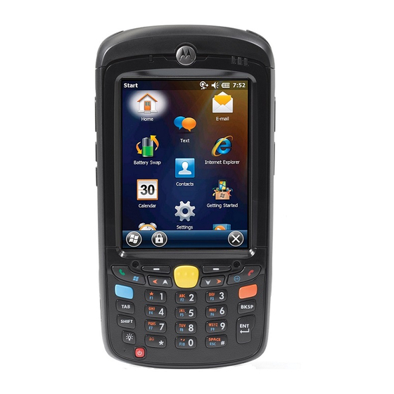
Motorola MC55A0 User Manual
Enterprise digital assistant
Hide thumbs
Also See for MC55A0:
- Quick start manual (2 pages) ,
- User manual (21 pages) ,
- Quick start manual (2 pages)
Table of Contents
Advertisement
Advertisement
Table of Contents
Troubleshooting

Related Manuals for Motorola MC55A0


Summary of Contents for Motorola MC55A0
- Page 1 MC55A0 MC55N0 ENTERPRISE DIGITAL ASSISTANT USER GUIDE...
- Page 3 MC55A0 MC55N0 ENTERPRISE DIGITAL ASSISTANT USER GUIDE 72E-148113-01 Rev. A August 2011...
- Page 4 Motorola. No right to copy a licensed program in whole or in part is granted, except as permitted under copyright law. The user shall not modify, merge, or incorporate any form or portion of a licensed program with other program material, create a derivative work from a licensed program, or use a licensed program in a network without written permission from Motorola.
-
Page 5: Revision History
Revision History Changes to the original guide are listed below: Change Date Description -01 Rev A 8/2011 Initial release. - Page 6 MC55A0/MC55N0 Enterprise Digital Assistant User Guide...
-
Page 7: Table Of Contents
Chapter 1: Getting Started Introduction ............................ 1-1 Unpacking ............................1-2 Getting Started ..........................1-3 Installing a microSD Card (MC55A0) ..................1-3 Installing a microSD Card (MC55N0) ..................1-4 Installing the Battery ........................ 1-5 Charging the Battery ........................ 1-6 Charging the Main Battery ....................1-6 Charging Spare Batteries .................... - Page 8 MC55A0/MC55N0 Enterprise Digital Assistant User Guide Turning Off the Radios ......................1-10 Handstrap Replacement ........................ 1-12 Removal ........................... 1-12 Installation ..........................1-13 Chapter 2: Operation Introduction ............................ 2-1 Finger Scrolling ..........................2-1 Home Screen ..........................2-1 Classic Today Screen ......................2-3 Status Bar ..........................
- Page 9 Table of Contents Using the RS507 Hands-free Imager ..................3-5 Digital Camera Scanning ....................... 3-5 DataWedge ............................ 3-6 Installation ..........................3-6 Enable DataWedge ........................3-6 Disable DataWedge ......................... 3-6 Taking Photos ..........................3-7 Recording Video ..........................3-7 Viewing Photos and Videos ......................3-7 Chapter 4: Bluetooth Introduction ............................
- Page 10 MC55A0/MC55N0 Enterprise Digital Assistant User Guide ActiveSync Using Serial Port Services ................4-27 Personal Area Network Services ..................4-28 A2DP/AVRCP Services ..................... 4-29 Connect to a HID Device ....................4-30 Bonding with Discovered Device(s) ..................4-30 Bluetooth Settings ........................4-32 Device Info .........................
- Page 11 Table of Contents Charging Temperature ....................... 5-14 Vehicle Holder ..........................5-15 Installation Reminders ......................5-15 Device Mounting Precautions ....................5-15 Installation ..........................5-16 Assembly ..........................5-16 Windshield Installation ....................... 5-16 Flat Surface Installation ...................... 5-17 Trigger Handle ..........................5-19 Inserting the MC55 into the Trigger Handle ................5-19 Removing the MC55 ........................
- Page 12 MC55A0/MC55N0 Enterprise Digital Assistant User Guide Four-slot Charge Only Cradle ....................A-7 Four-slot Ethernet Cradle ......................A-8 Magstripe Reader ........................A-9 Vehicle Cradle .......................... A-9 Cables ............................A-10 Appendix B: Keypads Numeric Keypad Configuration ....................B-1 Alpha-numeric Keypad Configurations ..................B-5 PIM Keypad Configuration .......................
-
Page 13: About This Guide
NOTE Screens and windows pictured in this guide are samples and can differ from actual screens. Documentation Set The documentation set for the MC55A0 and MC55N0 provides information for specific user needs, and includes: • MC55A0/MC55N0 Quick Start Guide - describes how to get the MC55A0 and MC55N0 EDA up and running. -
Page 14: Configurations
MC55A0/MC55N0 Enterprise Digital Assistant User Guide Configurations This guide covers the following configurations: Data Capture Operating Configuration Radios Display Memory Keypads Options System MC55A0 WLAN: 3.5” VGA 256 MB 1D laser Windows Numeric, 802.11a/b/g Color RAM/ scanner, Mobile QWERTY, 1 GB Flash 2D imager, 6.5.3... - Page 15 About This Guide xiii The second line lists the operating system version and the build number. The last part of the build number represents the AKU number. For example, Build 23137.5.3.9 indicates that the device is running AKU version 5.3.9. OEM Version To determine the OEM software version: >...
-
Page 16: Chapter Descriptions
Notational Conventions The following conventions are used in this document: • “EDA” and “MC55” refer to the Motorola MC55A0 and MC55N0 hand-held computers. • Italics are used to highlight the following: • Chapters and sections in this and related documents... -
Page 17: Related Documents
For the latest version of this guide and all guides, go to: http://supportcentral.motorola.com. Service Information If you have a problem with your equipment, contact Motorola Enterprise Mobility support for your region. Contact information is available at: http://www.motorola.com/enterprisemobility/contactsupport. When contacting Enterprise Mobility support, please have the following information available: •... - Page 18 MC55A0/MC55N0 Enterprise Digital Assistant User Guide Manufacturing label Motorola responds to calls by email, telephone or fax within the time limits set forth in support agreements. If your problem cannot be solved by Motorola Enterprise Mobility Support, you may need to return your equipment for servicing and will be given specific directions.
-
Page 19: Introduction
CHAPTER 1 GETTING STARTED Introduction This chapter lists the parts of the MC55 and explains how to set up the MC55 for the first time. Charging/Battery Scan/Decode Touch Screen with Status LED Protective Overlay Scan/Action Button Volume Up/Down Button Keypad (Alpha-Numeric Keypad Shown) Microphone Power Button... - Page 20 • Regulatory Guide • Quick Start Guide. Inspect the equipment for damage. If any equipment is missing or damaged, contact the Motorola Enterprise Mobility Support center immediately. See page xv for contact information. Prior to using the MC55 for the first time, remove the protective shipping film that covers the scan window,...
-
Page 21: Installing A Microsd Card (Mc55A0)
• Power on the MC55. Installing a microSD Card (MC55A0) The microSD card slot provides secondary non-volatile storage. The slot is located under the battery. Refer to the documentation provided with the card for more information, and follow the manufacturer’s recommendations for use. -
Page 22: Installing A Microsd Card (Mc55N0)
1 - 4 MC55A0/MC55N0 Enterprise Digital Assistant User Guide microSD card Holding tab Insert microSD Card in Holder Figure 1-4 Close the card holder door and push down until it is securely into place. Close SIM card holder door and slide down until it locks into place. -
Page 23: Installing The Battery
Getting Started 1 - 5 microSD card Holding tab Insert microSD Card in Holder Figure 1-6 Close the card holder door. Slide to the left to lock into place. Close rubber access door. Installing the Battery NOTE The MC55 ships with either a 2400 mAh or 3600 mAh battery. The 2400 mAh battery is shown in this installation procedure. -
Page 24: Charging The Battery
1 - 6 MC55A0/MC55N0 Enterprise Digital Assistant User Guide Charging the Battery CAUTION Ensure that you follow the guidelines for battery safety described in Battery Safety Guidelines on page 6-2. Charging the Main Battery Before using the MC55 for the first time, charge the main battery until the amber Charging/Battery Status LED... -
Page 25: Charging Spare Batteries
Getting Started 1 - 7 LED Charge Indicators (Continued) Table 1-1 Charging/Battery Indication Status LED Fast Blinking Amber Charging error, e.g.: (2 blinks/second) • Temperature is too low or too high. • Charging has gone on too long without completion (typically eight hours). Single Blink Amber (when Battery depleted. -
Page 26: Replacing The Battery
1 - 8 MC55A0/MC55N0 Enterprise Digital Assistant User Guide Replacing the Battery Press the red Power button to suspend the MC55. The PowerKey Action window appears. Tap Safe Battery Swap. The Decode LED lights red and then turns off. Unlatch the handstrap. -
Page 27: Removing The Microsd Card (Mc55N0)
Getting Started 1 - 9 Close SIM card holder door. Slide SIM card holder door down to lock into place. Close the rubber access door. Replace the battery. Re-attach the handstrap. Removing the microSD Card (MC55N0) To remove an microSD card: Press the red Power button to suspend the MC55. -
Page 28: Changing The Backlight Settings
1 - 10 MC55A0/MC55N0 Enterprise Digital Assistant User Guide Select the On battery power: Turn off device if not used for check box and select a value from the drop-down list. Select OK. Changing the Backlight Settings To change the backlight settings in order to conserve more battery power: >... - Page 29 Getting Started 1 - 11 Select Wireless Manager. Wireless Manager Window Figure 1-10 To enable or disable a wireless connection, tap the specific button. To enable or disable all wireless connections, tap and hold the All button. To configure settings for a connection, tap Menu.
-
Page 30: Handstrap Replacement
1 - 12 MC55A0/MC55N0 Enterprise Digital Assistant User Guide Handstrap Replacement Removal To remove the handstrap: Press the red Power button to suspend the MC55. The PowerKey Action window appears. Tap Safe Battery Swap. The Decode LED lights red and then turns off. -
Page 31: Installation
Getting Started 1 - 13 Handstrap and Pin Removal Figure 1-12 Repeat for the other side of the handstrap. Remove the pin from the handstrap. Pin Removal Figure 1-13 Pull the handstrap through the handstrap slot. Installation To install the handstrap: Feed the bottom end of the handstrap into the handstrap slot on the bottom of the MC55. - Page 32 1 - 14 MC55A0/MC55N0 Enterprise Digital Assistant User Guide Feed Handstrap into Handstrap Slot Figure 1-14 Slide the pin into the bottom of the handstrap. Center the pin in the handstrap loop. NOTE Handstrap and pin should fit securely into the handstrap mounting area. When pulling on handstrap use enough force to engage pin into place.
-
Page 33: Chapter 2 Operation
CHAPTER 2 OPERATION Introduction This chapter explains the buttons, status icons, and controls on the MC55, and provides basic instructions for using the MC55, including powering on and resetting. Finger Scrolling Finger scrolling can be used to scroll up and down web pages, documents, and lists such as the contacts list, file list, message list, calendar appointments list, and more. - Page 34 2 - 2 MC55A0/MC55N0 Enterprise Digital Assistant User Guide Status Bar Home Screen Tile Bar Open the Start Menu Tiles Windows Mobile Home Screen Figure 2-1 Touch and hold the screen with your finger and move the Home screen up and down. As the application names move under the Information Status bar, information relevant to that application appear in the bar.
-
Page 35: Classic Today Screen
Operation 2 - 3 Application Icon Application Information Information Bar Example Figure 2-4 To customize the screen, tap > > . On the horizontal scroll, use Home Settings Today Appearance customize the background and the to change the display format. Items Classic Today Screen The user can change to the classic Today screen layout that is used in Windows Mobile 6.1. -
Page 36: Status Bar
2 - 4 MC55A0/MC55N0 Enterprise Digital Assistant User Guide Home Screen Settings Figure 2-6 Deselect the Windows Default checkbox and select any of the other checkboxes. The task bar at the bottom of the screen can contain the task tray icons listed in Table 2-1. - Page 37 Operation 2 - 5 Notifications Connectivity Audio Battery Battery Clock Status Bar Icons Figure 2-7 Status Bar Icons Table 2-2 Icon Description Icon Description Notifications Indicates a reminder of an upcoming Notification that one or more instant calendar event. messages were received. Notification that one or more e-mail/text There are more notification icons than can messages were received.
-
Page 38: Tile Bar
2 - 6 MC55A0/MC55N0 Enterprise Digital Assistant User Guide Icon Bar Icon Bar Figure 2-8 Task Tray Icons Table 2-3 Icon Name Description Magnify Enlarges the screen. Notifications Indicates that notifications are available. Headset Indicates that a wireless stereo headset is connected to the MC55. - Page 39 Operation 2 - 7 Swipe upward to view more program and folder icons. Move often-used program and folder icons anywhere on the Start screen for easy access. Press and hold the icon and drag the icon to a new location and release. Table 2-4 lists the default icons available on the Start screen.
- Page 40 2 - 8 MC55A0/MC55N0 Enterprise Digital Assistant User Guide Programs on the Start Screen (Continued) Table 2-4 Icon Name Description Icon Name Description Calculator Perform basic arithmetic Tasks Keep track of your tasks. and calculations, such as addition, subtraction, multiplication, and division.
- Page 41 Requires the level of management purchase of an MSP client functionality required. license per device. DEMO Provides a link to Motorola’s BTExplorer Manages StoneStreet One featured demos. Bluetooth connections. Refer to the MC55 Series Mobile Computer Integrator Guide for more information.
- Page 42 2 - 10 MC55A0/MC55N0 Enterprise Digital Assistant User Guide Setting Applications (Continued) Table 2-5 Icon Name Description Icon Name Description Connections Folder Beam Set the MC55 to receive Connections Set up one or more types of incoming IrDA beams. Not modem connections for your supported on MC55.
-
Page 43: Ui Settings
Operation 2 - 11 Setting Applications (Continued) Table 2-5 Icon Name Description Icon Name Description Memory Check the device memory Regional Set the regional allocation status and Settings configuration to use, memory card information including the format for and stop currently running displaying numbers, programs. -
Page 44: Ie Zoom Mapping
2 - 12 MC55A0/MC55N0 Enterprise Digital Assistant User Guide Start Screen Settings Tab Figure 2-10 Select the number of columns. Tap OK. NOTE Tap Reset to return to the default 3 Column setting. Tap OK. Preform a warm boot. IE Zoom Mapping When Internet Explorer opens, the volume keys on the side of the MC55 are used to zoom in and out. -
Page 45: Locking The Mc55
Operation 2 - 13 Locking the MC55 Lock the MC55 by disabling key presses and screen tap or by requiring a password. Locking the MC55 turns off keyboard and touch screen functionality. This is helpful when the MC55 is turned on and you want to prevent accidental key presses. -
Page 46: Locking With Strong Password
2 - 14 MC55A0/MC55N0 Enterprise Digital Assistant User Guide Locking with Strong Password When the MC55 is locked, the Lock screen appears. Strong Password Lock Screen Figure 2-14 Enter the strong password and then tap Unlock. Password Locking Setup Use the window to set a password to disable unauthorized access to the MC55. -
Page 47: Battery Status Indications
Operation 2 - 15 Enter a seven character password in the field. A strong password must contain at least Password: seven characters and contain at least three of the following: uppercase and lowercase letters, numerals, and punctuation. Re-enter the password in the field. -
Page 48: Battery Reserve Options
2 - 16 MC55A0/MC55N0 Enterprise Digital Assistant User Guide Battery Reserve Options If the charge of the battery reaches a critical threshold, the MC55 shuts down. This threshold can be changed but affects the amount of time that data can be retained. -
Page 49: Battery Health
Operation 2 - 17 • Level 1: Temperature Watch; this level is similar to main battery low warning. It indicates that the battery temperature has reached the first threshold level. The user should move to an environment within proper operating temperature. •... - Page 50 2 - 18 MC55A0/MC55N0 Enterprise Digital Assistant User Guide Battery Management Dialog Box Figure 2-22 Battery Information Table 2-6 Item Description State of Health Indicates the current state of the battery (Healthy or Unhealthy). Battery Usage Indicator Indicates the usage of the battery.
-
Page 51: Led Indicators
Operation 2 - 19 LED Indicators The MC55 has three LED indicators. The Scan/Decode LED indicates status for scanning. The Charging/Battery Status LED indicates battery charging and status. Charging/Battery Charging/Battery Scan/Decode Status LED Status LED LED Indicators Figure 2-23 LED Indications Table 2-7 LED State Indication... -
Page 52: Performing A Warm Boot
2 - 20 MC55A0/MC55N0 Enterprise Digital Assistant User Guide Performing a Warm Boot Hold down the red Power button for approximately five seconds. As soon as the MC55 starts to boot (splash screen displays) release the Power button. Performing a Cold Boot To perform a cold boot: •... -
Page 53: Function Buttons
Drag: Hold the stylus on the screen and drag across the screen to select text and images. Drag in a list to select multiple items. CAUTION To prevent damage to the screen, do not use any device other than the Motorola-provided stylus. -
Page 54: Entering Data
NOTE future update. The MC55 supports Voice over IP over WLAN (VoWLAN) using Motorola or third party voice clients. The MC55 can communicate using VoIP either using the MC55 supports several audio outputs, including back speaker phone, front receiver or handset, and Bluetooth headset. -
Page 55: Interactive Sensor Technology
Operation 2 - 23 Interactive Sensor Technology The Interactive Sensor Technology (IST) supports the following features: • Power Management – manages power by configuring IST to control switching on/off the backlight, control suspend mode of the MC55 by monitoring motion and orientation. •... -
Page 56: Usb Configuration
2 - 24 MC55A0/MC55N0 Enterprise Digital Assistant User Guide USB Configuration The MC55 can be placed into any of the following USB modes: • USB Client - Sets the MC55 to USB Client mode. • USB Host - Sets the MC55 to USB Host mode. -
Page 57: Chapter 3 Data Capture
Digital camera. NOTE To perform data capture a scanning enabled application must be installed on the MC55. A sample scanning application can be downloaded from the Motorola Support site at http://support.symbol.com. Linear Scanning MC55 with an integrated linear scanner have the following features: •... -
Page 58: Operational Modes
3 - 2 MC55A0/MC55N0 Enterprise Digital Assistant User Guide Operational Modes MC55 with an integrated imager support three modes of operation, listed below. Activate each mode by pressing the Scan button. • Decode Mode: In this mode, the MC55 attempts to locate and decode enabled bar codes within its field of view. -
Page 59: Linear Scanning
Data Capture 3 - 3 NOTE Scanning procedures depend on the application and MC55 configuration. An application may use different scanning procedures from the one listed above. Linear Scanning To read a bar code, a scan-enabled application is required. The MC55 contains the DataWedge application that allows the user to enable the scanner to decode bar code data and display the bar code content. - Page 60 3 - 4 MC55A0/MC55N0 Enterprise Digital Assistant User Guide Imager Scanning Figure 3-3 Press the scan button. The red laser aiming pattern or aiming dot turns on to assist in aiming. Ensure the bar code is within the area formed by the brackets in the aiming pattern or close to the aiming dot. The aiming dot is used for increased visibility in bright lighting conditions.
-
Page 61: Using The Rs507 Hands-Free Imager
Data Capture 3 - 5 Using the RS507 Hands-free Imager An RS507 Hands-free Imager can be used with the MC55 to capture bar code data. To set up the MC55 and RS507: > BTScannerCtlPanel icon. Select the BT Scanner checkbox and then select the appropriate Com port from the drop-down list. Tap Save and Exit. -
Page 62: Datawedge
3 - 6 MC55A0/MC55N0 Enterprise Digital Assistant User Guide DataWedge NOTE On MC55N0, by default, DataWedge is loaded but not installed on the MC55. An installation file resides in the Windows folder. Installation NOTE For MC55N0 only. To install DataWedge: >... -
Page 63: Taking Photos
Data Capture 3 - 7 Tap OK. Taking Photos To take a photo: > Programs > Pictures & Videos icon. Tap Camera on the command bar. Check the image on the view finder, adjust if necessary. Press the Enter key to take the picture. Hold the MC55 still until the shutter sound is heard. Recording Video To record a video clip: >... - Page 64 3 - 8 MC55A0/MC55N0 Enterprise Digital Assistant User Guide...
-
Page 65: Chapter 4 Bluetooth
Hop Sequence Modification - Avoids interference by selectively reducing the number of hopping channels. • Channel Maintenance - A method for periodically re-evaluating the channels. When AFH is enabled, the Bluetooth radio “hops around” (instead of through) the 802.11b high-rate channels. AFH coexistence allows Motorola mobile computers to operate in any infrastructure. -
Page 66: Security
4 - 2 MC55A0/MC55N0 Enterprise Digital Assistant User Guide The Bluetooth radio in this MC55 operates as a Class 2 device power class. The maximum output power is 2.5mW and the expected range is 32.8 feet (10 meters). A definition of ranges based on power class is difficult to obtain due to power and device differences, and whether one measures open space or closed office space. -
Page 67: Bluetooth Configuration
Bluetooth 4 - 3 Bluetooth Configuration By default, the MC55 is configured to using the Microsoft Bluetooth stack. Refer to the MC55 Integrator Guide, Appendix B, for information on switching to the StoneStreet One Bluetooth stack. Table 4-1 list the services supported by the Microsoft Bluetooth stack and the StoneStreet One Bluetooth stack. Bluetooth Services Table 4-1 Microsoft Bluetooth Stack... -
Page 68: Bluetooth Power States
4 - 4 MC55A0/MC55N0 Enterprise Digital Assistant User Guide Bluetooth Power States Cold Boot With StoneStreet One Bluetooth Stack Performing a cold boot on the MC55 turns off Bluetooth after initialization (which takes a few moments). It is normal to see the Bluetooth icon appear and disappear (when using the Classic Home screen), as well as a wait cursor, when initialization proceeds in all modes. -
Page 69: Using Microsoft Bluetooth Stack
Bluetooth 4 - 5 Using Microsoft Bluetooth Stack The following sections provide information on using the Microsoft Bluetooth stack. Turning the Bluetooth Radio Mode On and Off NOTE On devices with Windows Mobile 6.5.3, turn the Bluetooth radio on or off using the Wireless Manager. Tap the Status bar and select the Connectivity icon. -
Page 70: Discovering Bluetooth Device(S)
4 - 6 MC55A0/MC55N0 Enterprise Digital Assistant User Guide Discovering Bluetooth Device(s) The MC55 can receive information from discovered devices without bonding. However, once bonded, the MC55 and a bonded device exchange information automatically when you turn the Bluetooth radio on. See Bonding with Discovered Device(s) on page 4-30 for more information. - Page 71 Bluetooth 4 - 7 Select a Bluetooth Device Figure 4-4 Tap Next. The Enter Passcode window appears. NOTE If Smart-pairing is configured and the device is requesting one of the pre-defined PINs, the Enter Passcode window does not appear. Enter Passcode Figure 4-5 Enter the Passcode on the other device.
-
Page 72: Available Services
4 - 8 MC55A0/MC55N0 Enterprise Digital Assistant User Guide Available Services NOTE Some devices might not require a PIN. This depends upon the device’s authentication. The MC55 with Microsoft Bluetooth stack offers the following services: • OBEX Object Push Services via Beam •... -
Page 73: Internet Sharing
Bluetooth 4 - 9 Beam File Window Figure 4-7 To transfer a contact between the MC55 and another Bluetooth enabled device: Ensure that Bluetooth is enabled and discoverable on both devices. Ensure that the two devices are within 30 feet (10 meters) of one another. >... -
Page 74: Serial Port Services
4 - 10 MC55A0/MC55N0 Enterprise Digital Assistant User Guide Tap > Programs > Internet Sharing. In the PC Connection list, select Bluetooth PAN. In the Network Connection list, select the connection type. Select the network connection that the device should use to connect to the Internet. -
Page 75: Activesync Using Serial Port Services
Bluetooth 4 - 11 NOTE By default, Secure Connection checkbox is set enabling Security Level 3 (Linked Level Encryption). Select the serial device in the list and then tap Next. Select a COM port from the drop-down list. Tap Finish. NOTE No connection is made at this point. - Page 76 4 - 12 MC55A0/MC55N0 Enterprise Digital Assistant User Guide Computer Bluetooth Devices Window Figure 4-9 On the COM Ports tab, click Add. Select the Incoming (device initiates the connection) option, then click OK. Note the number of the COM port that was added.
-
Page 77: Phone Book Access Profile Services
Bluetooth 4 - 13 If an Authentication is required, the Enter Passcode screen appears, type an alphanumeric passkey (PIN code), then tap Next; enter the same passkey on the other device. The passkey is recommended for enhanced security. Your passkey must be between 1 to 16 alphanumeric characters. -
Page 78: Using Bluetooth Stonestreet One Bluetooth Stack
4 - 14 MC55A0/MC55N0 Enterprise Digital Assistant User Guide Using Bluetooth StoneStreet One Bluetooth Stack The following sections provide information on using the Stone Street One Bluetooth stack. Turning the Bluetooth Radio Mode On and Off Turn off the Bluetooth radio to save power or if entering an area with radio restrictions (e.g., an airplane). When the radio is off, other Bluetooth devices cannot see or connect to the MC55. -
Page 79: Discovering Bluetooth Device(S)
Bluetooth 4 - 15 Explorer Mode Window Figure 4-11 You can also use the “tap and hold” technique to view available options. Scroll bars and view options are similar to those on the Windows desktop. The tree structure lists the following sub-items: •... - Page 80 4 - 16 MC55A0/MC55N0 Enterprise Digital Assistant User Guide BTExplorer Window Figure 4-12 Select Explore Services on Remote Device or another from the drop-down list and tap Next. NOTE If a device discovery action has not been previously performed, a device discovery is automatically initiated.
- Page 81 Bluetooth 4 - 17 Select Remote Device Window Figure 4-14 Select a device from the list and tap Next. The MC55 searches for services on the selected Bluetooth device. Device Services Figure 4-15 NOTE If the MC55 discovers a service but the service is not supported, the service icon is grayed-out. Select a service from the list and press Next.
-
Page 82: Available Services
4 - 18 MC55A0/MC55N0 Enterprise Digital Assistant User Guide Tap Next. The Connection Summary window appears. Tap Connect to add the service to the Favorite window and connect to the service. Favorites Window Figure 4-17 Available Services NOTE Some devices might not require a PIN. This depends upon the device’s authentication. - Page 83 Bluetooth 4 - 19 File Transfer Window Figure 4-18 Double-tap the file to copy. The Save Remote File window appears. Save Remote File Window Figure 4-19 Tap and hold on the file. A pop-up menu appears. Select the action to perform: •...
-
Page 84: Connecting To The Internet Using An Access Point
4 - 20 MC55A0/MC55N0 Enterprise Digital Assistant User Guide Tap and hold on the file to delete and select Delete. In the Delete Remote Device File dialog box tap Yes. Getting a File To copy a file from a remote device: Double-tap or tap and hold on the file and select Get. - Page 85 Bluetooth 4 - 21 Ensure the Bluetooth Phone is discoverable and connectable. Ensure that the Dial-Up Networking profile is enabled on the MC55. See Profiles on page 4-39 for more information. Tap Menu > New Connection. Select Explore Services on Remote Device or another from the drop-down list and tap Next. BTExplorer searches for Bluetooth devices in the area.
-
Page 86: Add A Dial-Up Entry
4 - 22 MC55A0/MC55N0 Enterprise Digital Assistant User Guide Select Dial-up Networking Entry Window Figure 4-22 Select the entry and tap OK. The MC55 begins to communicate with the Bluetooth phone. If required, the phone requests permission to communicate with the MC55. -
Page 87: Object Exchange Push Services
Bluetooth 4 - 23 Add Phone Book Entry Window Figure 4-24 In the Name for the connection text box, enter a name for this connection. In the Country Code text box, enter the country code for the country that you are calling. In the Area Code text box, enter the area code. - Page 88 4 - 24 MC55A0/MC55N0 Enterprise Digital Assistant User Guide Sending a Contact To send a contact to another device: NOTE Prior to sending and receiving contacts, a default contact must be set up before attempting to send a contact. Tap and hold on OBEX Object Push and select Connect.
- Page 89 Bluetooth 4 - 25 OBEX Object Push Window Figure 4-26 In the Action: drop-down list, select Swap Contact Information. . The Select Contact Entry window appears. Select a contact to send to the other device. Tap OK. Tap OK to swap contacts with the other device and display a confirmation dialog box on the other device to accept the contact.
-
Page 90: Headset Services
4 - 26 MC55A0/MC55N0 Enterprise Digital Assistant User Guide Sending a Picture To send a picture to another device: Tap and hold on OBEX Object Push and select Connect. The OBEX Object Push window appears. OBEX Object Push Window Figure 4-28 In the Action: drop-down list, select Send A Picture. -
Page 91: Serial Port Services
Bluetooth 4 - 27 Ensure the MC55 is connectable (required when automatic re-connect is initiated). See Device Info on page 4-32. Ensure that the Headset profile is enabled on the MC55. See Profiles on page 4-39 for more information. Use the Connection Wizard to search for a Bluetooth headset. Select the device and tap Next. -
Page 92: Personal Area Network Services
4 - 28 MC55A0/MC55N0 Enterprise Digital Assistant User Guide ActiveSync Connection Settings Window on PC Figure 4-30 To establish an ActiveSync connection: NOTE When creating an ActiveSync connection, only use StoneStreet One Bluetooth Explorer in Wizard mode. Use the Connection Wizard to search for a Bluetooth device, such as a computer. In the drop-down list select ActiveSync via Bluetooth. -
Page 93: A2Dp/Avrcp Services
Bluetooth 4 - 29 Connect two or more Bluetooth devices to share files, collaborate, or play multi-player games. To establish a Personal Area Network connection: Ensure that the Personal Area Networking profile is enabled on the MC55. See Profiles on page 4-39 for more information. -
Page 94: Connect To A Hid Device
4 - 30 MC55A0/MC55N0 Enterprise Digital Assistant User Guide Tap Next. Tap Connect. Connect to a HID Device The MC55 can connect to an Human Interface Device (HID) device such as a Bluetooth keyboard: Ensure the MC55 is connectable (required when automatic re-connect is initiated). See Device Info on page 4-32. - Page 95 Bluetooth 4 - 31 Select Remote Device Window Figure 4-32 Select a device from the list and tap Next. The PIN Code Request window appears. Connection Favorite Options Window Figure 4-33 In the PIN Code field, enter the PIN code. Tap OK.
-
Page 96: Bluetooth Settings
4 - 32 MC55A0/MC55N0 Enterprise Digital Assistant User Guide PIN Code Request Window Figure 4-34 In the PIN Code: text box, enter the same PIN entered on the device requesting the bond. The PIN must be between 1 and 16 characters. - Page 97 Bluetooth 4 - 33 BTExplorer Settings - Services Figure 4-35 To add a service: Tap Add. Add Local Service Window Figure 4-36 In the list, select a service to add. Tap OK. The Edit Local Service window displays for the selected service. Select the appropriate information and then tap OK.
- Page 98 4 - 34 MC55A0/MC55N0 Enterprise Digital Assistant User Guide Dial-up Networking Information Data Table 4-4 Item Description Local COM Port Select the COM port. Local Baud Rate Select the communication baud rate. Local Port Options Select the port option. File Transfer Service File transfer allows other Bluetooth devices to browse files.
- Page 99 Bluetooth 4 - 35 Headset Audio Gateway Data Table 4-7 Item Description Service Name Lists the name of the audio service. IrMC Synchronization Service The IrMC Synchronization service used to synchronize PIM contacts between a remote device and the MC55. IrMC Synchronization Data Table 4-8 Item...
-
Page 100: Security
4 - 36 MC55A0/MC55N0 Enterprise Digital Assistant User Guide Serial Port Service Serial port allows other Bluetooth devices to access COM ports. Serial Port Services Data Table 4-11 Item Description Service Name Displays the name of the service. Service Security Select the type of security from the drop-down list. -
Page 101: Discovery
Bluetooth 4 - 37 BTExplorer Settings - Security Figure 4-38 Authenticate Authenticate/Encrypt NOTE To use PIN Code, select from the Service Security drop-down list on each local service. Security Data Table 4-14 Item Description Use PIN Code (Incoming Select for automatic use of the PIN code entered in the PIN Code text Connection) box. -
Page 102: Virtual Com Port
4 - 38 MC55A0/MC55N0 Enterprise Digital Assistant User Guide Discovery Data Table 4-15 Item Description Inquiry Length Sets the amount of time the MC55 takes to discover Bluetooth devices in the area. Name Discovery Mode Select either Automatic or Manual to automatically attempt to discover a Bluetooth device's name after finding the device. -
Page 103: Profiles
Bluetooth 4 - 39 Profiles Use Profile to load or remove Bluetooth services profiles. If a profile is not used, it can be removed to save memory. Tap a check box next to the profile to load (activate). The Serial Port profile is always active and cannot be removed. Tap Select All to select all profiles or tap Deselect All to deselect all profiles. - Page 104 4 - 40 MC55A0/MC55N0 Enterprise Digital Assistant User Guide...
-
Page 105: Chapter 5 Accessories
CHAPTER 5 ACCESSORIES Introduction Table 5-1 lists the accessories available for the MC55. MC55 Accessories Table 5-1 Accessory Part Number Description Cradles Single-slot USB Cradle CRD5500-1000UR Charges the MC55 main battery and a spare battery. Synchronizes the MC55 with a host computer through a USB connection. - Page 106 5 - 2 MC55A0/MC55N0 Enterprise Digital Assistant User Guide MC55 Accessories (Continued) Table 5-1 Accessory Part Number Description Spare 2400 mAh lithium-ion BTRY-MC55EAB00 Replacement 2400 mAh battery (MC55 only). battery BTRY-MC55EAB00-10 10-pack. BTRY-MC55EAB00-50 50-pack. Spare 3600 mAh lithium-ion BTRY-MC55EAB02 Replacement 3600 mAh battery.
-
Page 107: Single-Slot Usb Cradle
Accessories 5 - 3 Single-slot USB Cradle This section describes how to use a Single-slot USB cradle with the MC55. For USB communication setup procedures refer to the MC55 Integrator Guide. The Single-slot USB Cradle: • Provides 5.4 VDC power for operating the MC55. •... -
Page 108: Charging The Spare Battery
5 - 4 MC55A0/MC55N0 Enterprise Digital Assistant User Guide Charging the Spare Battery Spare Battery Spare Battery Charging LED Spare Battery Charging Figure 5-2 Battery Charging Indicators The Single-slot USB Cradle charges the MC55’s main battery and a spare battery simultaneously. - Page 109 Accessories 5 - 5 Spare Battery LED Charging Indicators Table 5-2 Spare Battery LED Indication (on cradle) Battery is not charging; battery is not inserted correctly in the cradle; cradle is not powered Slow Blinking Amber Spare battery is charging. Solid Amber Charging complete.
-
Page 110: Single-Slot Ethernet/Modem/Usb Cradle
The modem defaults to operation with US telephone networks. To operate the modem with other country telephone networks, it must be configured using an application on the MC55. Download the Cradle Modem Country Configurator Application Software for MC55xx package from the Motorola Support Central web site: http://www.motorola.com/enterprisemobility/support. -
Page 111: Indicators
Accessories 5 - 7 Indicators Spare Battery Ethernet/Modem LED Speed LED Link LED Charging Indicators Figure 5-5 • Spare Battery Charging LED - Indicates the charging status of the spare battery. • Ethernet/Modem LED - Blink whenever Ethernet or modem connectivity is established. •... -
Page 112: Four-Slot Charge Only Cradle
5 - 8 MC55A0/MC55N0 Enterprise Digital Assistant User Guide Four-slot Charge Only Cradle This section describes how to set up and use a Four-slot Charge Only cradle with the MC55. The Four-slot Charge Only cradle: • Provides 5.4 VDC power for operating the MC55. -
Page 113: Four-Slot Ethernet Cradle
Accessories 5 - 9 Four-slot Ethernet Cradle This section describes how to set up and use a Four-slot Ethernet cradle with the MC55. For cradle communication setup procedures refer to the MC55 Integrator Guide. The Four-slot Ethernet cradle: • Provides 5.4 VDC power for operating the MC55. •... -
Page 114: Vcd5000 Vehicle Cradle
CAUTION Ensure the MC55 is fully inserted in the cradle. Lack of proper insertion may result in property damage or personal injury. Motorola is not responsible for any loss resulting from the use of the products while driving. Removing the MC55... -
Page 115: Battery Charging Indicators
Accessories 5 - 11 Release Lever Removing the MC55 Figure 5-9 Battery Charging Indicators The MC55’s charge LED indicates the status of the battery charging in the MC55. See Table 1-1 on page 1-6 for charging status indications. The 2400 mAh battery fully charges in less than four hours and the 3600 mAh battery fully charges in less than six hours. -
Page 116: Four-Slot Battery Charger
5 - 12 MC55A0/MC55N0 Enterprise Digital Assistant User Guide Four-slot Battery Charger This section describes how to use the Four-slot Battery Charger to charge up to four MC55 batteries. Battery Charging Connect the charger to a power source. Insert the battery into a battery charging well and gently press down on the battery to ensure proper contact. -
Page 117: Cables
The following communication/charge cables are available: • USB Charging cable • Provide the MC55 with operating and charging power when used with the Motorola approved power supply. • Synchronize information between the MC55 and a host computer. With customized or third party software, it can also synchronize the MC55 with corporate databases. -
Page 118: Led Charge Indications
5 - 14 MC55A0/MC55N0 Enterprise Digital Assistant User Guide Locking Tab Cable Cup Locking Tabs Figure 5-11 The MC55 amber Charge LED indicates the MC55 battery charging status. The 2400 mAh standard battery charges in less than four hours and the 3600 mAh standard battery charges in less than six hours. -
Page 119: Vehicle Holder
Accessories 5 - 15 To accomplish this, for small periods of time, the MC55 or accessory alternately enables and disables battery charging to keep the battery at acceptable temperatures. The MC55 or accessory indicates when charging is disabled due to abnormal temperatures via its LED. See Table 1-1 on page 1-6. -
Page 120: Installation
5 - 16 MC55A0/MC55N0 Enterprise Digital Assistant User Guide Installation Install the vehicle mount on the surface of your vehicle that is reasonably flat and free of dirt and oil. Clean the mounting surface with a glass cleaner and a clean cotton cloth. Install the vehicle mount on the windshield or other flat car surface using the supplied mounting disc. -
Page 121: Flat Surface Installation
Accessories 5 - 17 Locking Tab Insert MC55 into Vehicle Holder Figure 5-14 Connect the auto charger cable to the MC55 and slide the two locking tabs up to secure the cable cup to the MC55. Connect the other end to the cigarette lighter socket. The LED indicator on the right side of the touch screen lights up orange during charging. - Page 122 5 - 18 MC55A0/MC55N0 Enterprise Digital Assistant User Guide Vehicle Holder Mounted on Flat Surface Figure 5-16 Connect the auto charger cable to the MC55 and slide the two locking tabs up to secure the cable cup to the MC55.
-
Page 123: Trigger Handle
Accessories 5 - 19 Trigger Handle The TRG5500 Trigger Handle adds a gun-style handle with a scanning trigger to the MC55. It increases comfort when using the MC55 in scan-intensive applications for extended periods of time. Latch Trigger Release Button Trigger Handle Features Figure 5-17 Inserting the MC55 into the Trigger Handle... -
Page 124: Scanning
5 - 20 MC55A0/MC55N0 Enterprise Digital Assistant User Guide Scanning To scan bar codes: NOTE A scanning application must be installed prior to scanning a bar code. Start the MC55’s scanning application. Aim the MC55 at the bar code. Press the trigger on the handle. The Scan/Decode LED lights and a beep sounds to indicate a successful decode. -
Page 125: Chapter 6 Maintenance & Troubleshooting
Never use an actual pen or pencil or other sharp object on the surface of the MC55 screen. Motorola recommends using a screen protector, p/n KT-67525-01R. • The touch-sensitive screen of the MC55 is glass. Do not to drop the MC55 or subject it to strong impact. -
Page 126: Removing The Screen Protector
• Quick and easy installation. Removing the Screen Protector A screen protector is applied to the MC55. Motorola recommends using this to minimize wear and tear. Screen protectors enhance the usability and durability of touch screen displays. To remove the screen protector, lift the corner using a thin plastic card, such as a credit card, then carefully lift it off the display. -
Page 127: Cleaning
Always wear eye protection. Read warning label on compressed air and alcohol product before using. If you have to use any other solution for medical reasons please contact Motorola for more information. WARNING Avoid exposing this product to contact with hot oil or other flammable liquids. If such exposure occurs, unplug the device and clean the product immediately in accordance with these guidelines. -
Page 128: Harmful Ingredients
6 - 4 MC55A0/MC55N0 Enterprise Digital Assistant User Guide Harmful Ingredients The following chemicals are known to damage the plastics on the MC55 and should not come in contact with the device: ammonia solutions, compounds of amines or ammonia; acetone; ketones; ethers; aromatic and chlorinated hydrocarbons;... -
Page 129: Cleaning Cradle Connectors
Maintenance & Troubleshooting 6 - 5 Rub the cotton portion of the cotton tipped applicator back-and-forth across the connector on the bottom of the MC55. Do not leave any cotton residue on the connector. Repeat at least three times. Use the cotton tipped applicator dipped in alcohol to remove any grease and dirt near the connector area. Use a dry cotton tipped applicator and repeat steps 4 through 6. -
Page 130: Troubleshooting
6 - 6 MC55A0/MC55N0 Enterprise Digital Assistant User Guide Troubleshooting MC55 Troubleshooting the MC55 Table 6-1 Problem Cause Solution When pressing the Battery not charged. Charge or replace the battery in the MC55. power button the Battery not installed Install the battery properly. See Installing the Battery on page MC55 does not turn properly. - Page 131 Maintenance & Troubleshooting 6 - 7 Troubleshooting the MC55 (Continued) Table 6-1 Problem Cause Solution MC55 shuts off. MC55 is inactive. The MC55 turns off after a period of inactivity. If the MC55 is running on battery power, set this period from 1 to 5 minutes, in one-minute intervals.
-
Page 132: Bluetooth Connection
6 - 8 MC55A0/MC55N0 Enterprise Digital Assistant User Guide Troubleshooting the MC55 (Continued) Table 6-1 Problem Cause Solution The MC55 does not Scanning Load a scanning application on the MC55. See your system decode with reading application is not administrator. -
Page 133: Single-Slot Usb Cradle
Maintenance & Troubleshooting 6 - 9 Single-slot USB Cradle Troubleshooting the Single-slot USB Cradle Table 6-3 Symptom Possible Cause Action LEDs do not light Cradle is not Ensure the power cable is connected securely to both the when MC55 or spare receiving power. -
Page 134: Four-Slot Ethernet Cradle
6 - 10 MC55A0/MC55N0 Enterprise Digital Assistant User Guide Four-slot Ethernet Cradle Troubleshooting the Four-slot Ethernet Cradle Table 6-4 Symptom Cause Solution Attempt by the MC55 MC55 removed Wait one minute and reinsert the MC55 in the cradle. This to ActiveSync failed. -
Page 135: Vehicle Cradle
Maintenance & Troubleshooting 6 - 11 Troubleshooting the Four-slot Ethernet Cradle (Continued) Table 6-4 Symptom Cause Solution Battery is not MC55 removed Replace the MC55 in the cradle. The 2400 mAh battery fully charging. from the cradle too charges in less than four hours and the 3600 mAh battery fully soon. -
Page 136: Four-Slot Battery Charger
6 - 12 MC55A0/MC55N0 Enterprise Digital Assistant User Guide Four-slot Battery Charger Troubleshooting The Four-slot Battery Charger Table 6-6 Symptom Possible Cause Action Battery not charging. Battery was Re-insert the battery in the charger or re-connect the charger’s removed from the power supply. -
Page 137: Magnetic Stripe Reader
Trigger Handle and is not making Handle and reinsert. contact with the connector. MC55 does not contain a scanning Load a scanning application on the application. MC55. Refer to the MC55A0/N0 Integrator Guide. Scanning application is not active. Start the scanning application. - Page 138 6 - 14 MC55A0/MC55N0 Enterprise Digital Assistant User Guide Trigger Handle (Continued) Table 6-9 Problem Cause Solution MC55 battery does not Trigger Handle is not properly seated Remove the Trigger Handle from the charge when Trigger Handle in the cradle.
-
Page 139: Appendix A Technical Specifications
APPENDIX A TECHNICAL SPECIFICATIONS MC55 Technical Specifications The following tables summarize the MC55’s intended operating environment and technical hardware specifications. MC55 MC55 Technical Specifications Table A-1 Item Description Physical Characteristics Dimensions (2400 mAh battery): Height: 14.7 cm (5.78 in.) Width: 7.7 cm (3.03 in.) Depth: 2.7 cm (1.06 in.) (3600 mAh battery): Height: 14.7 cm (5.78 in.) - Page 140 A - 2 MC55A0/MC55N0 Enterprise Digital Assistant User Guide MC55 Technical Specifications (Continued) Table A-1 Item Description Network Connections Full-speed USB, host or client, Bluetooth and WiFi. USB host mode available with appropriate cables only. Notification LED and audible alert Keypad Options 26-key numeric;...
- Page 141 Division Multiplexing (OFDM) Antenna Internal Voice Communication Note: Currently supported on the MC55A0. It will be supported on MC55N0 in a future update. Voice-over-IP ready (with P2P, PBX, PTT clients), Wi-Fi™-certified, IEEE 802.11 a/b/g direct sequence wireless LAN, Wi-Fi Multimedia™ (WMM),...
- Page 142 2,000 +/- 5% G Aiming Element (VLD) 655 nm +/- 10 nm Illumination Element (LED) 625 nm +/- 5 nm LEDs (2x) 2D Imager Engine (SE4500-HD) Specifications (MC55A0 only) Field of View Horizontal - 38.4° Vertical - 24.9° Optical Resolution...
- Page 143 Specifications A - 5 MC55 Technical Specifications (Continued) Table A-1 Item Description Illumination Element (LED) 625 nm +/- 5 nm LEDs (2x) Camera Specifications Resolution 3 Mega pixel with flash and auto focus. Data Capture Options Table A-2 Item Description Laser Decode Capability Code 39 Code 128...
-
Page 144: Mc55 Accessory Specifications
A - 6 MC55A0/MC55N0 Enterprise Digital Assistant User Guide MC55 Accessory Specifications Single-slot USB Cradle Single-slot USB Cradle Technical Specifications Table A-3 Feature Description Dimensions Height: 7.1 cm (2.80 in.) Width: 11.0 cm (4.33 in.) Depth: 15.0 cm (5.91 in.) Weight 210 g (7.41 oz) -
Page 145: Four-Slot Battery Charger
Specifications A - 7 Single-slot Ethernet/Modem/USB Cradle Technical Specifications (Continued) Table A-4 Feature Description Humidity 5% to 95% non-condensing Drop 76.2 cm (30.0 in.) drops to vinyl tiled concrete at room temperature Electrostatic Discharge (ESD) +/- 15 kV air +/- 8 kV contact Four-slot Battery Charger Four-slot Battery Charger Technical Specifications Table A-5... -
Page 146: Four-Slot Ethernet Cradle
A - 8 MC55A0/MC55N0 Enterprise Digital Assistant User Guide Four-slot Charge Only Cradle Technical Specifications (Continued) Table A-6 Feature Description Storage Temperature -40°C to 70°C (-40°F to 158°F) Charging Temperature 0°C to 40°C (32°F to 104°F) Humidity 5% to 95% non-condensing Drop 76.2 cm (30.0 in.) drops to vinyl tiled concrete at room temperature... -
Page 147: Magstripe Reader
Specifications A - 9 Magstripe Reader Magstripe Reader (MSR) Technical Specifications Table A-8 Feature Description Dimensions 8.4 cm x 9.4 cm (3.3 inches x 3.7 inches) Weight 79.4 g (2.8 oz.) Interface Serial with baud rate up to 19,200 Format ANSI, ISO, AAMVA, CA DMV, user-configurable generic format Swipe Speed 5 to 50 in. -
Page 148: Cables
A - 10 MC55A0/MC55N0 Enterprise Digital Assistant User Guide Cables USB Charging Cable Technical Specifications Table A-10 Feature Description Length 161.9 cm (63.74 in.) Input Voltage 5.4 VDC Operating Temperature -10°C to 50°C (14°F to 122°F) Storage Temperature -40°C to 70°C (-40°F to 158°F) - Page 149 Specifications A - 11 DEX Cable Technical Specifications Table A-13 Feature Description Length 111.76 cm (44.0 in.) Operating Temperature -10°C to 50°C (14°F to 122°F) Storage Temperature -40°C to 70°C (-40°F to 158°F) Humidity 10% to 95% non-condensing Electrostatic Discharge (ESD) +/- 15 kV air +/- 8 kV contact...
- Page 150 A - 12 MC55A0/MC55N0 Enterprise Digital Assistant User Guide...
-
Page 151: Appendix B Keypads
APPENDIX B KEYPADS The MC55 offers three types of keypad configurations: Numeric, alpha-numeric and PIM (available on the MC55N0 in a future release). Numeric Keypad Configuration The numeric keypad contains application keys, scroll keys, and function keys. The keypad is color-coded to indicate the alternate function key (blue) values. - Page 152 [where xx is the new APP key code] Provision the file to the MC55 to send an APP key code, instead of the original key code, upon pressing the green phone key. Refer to the MC55A0/MC55N0 Integrator Guide for information on creating XML provisioning files.
- Page 153 Keypads B - 3 MC55 Numeric Keypad Descriptions (Continued) Table B-1 Description Scroll Up and Left Moves up one item. Moves left one item when pressed with the Orange key. Scroll Down and Moves down one item. Right Moves right one item when pressed with the Orange key. Soft Keys Accesses the command or menu above it on the screen.
- Page 154 B - 4 MC55A0/MC55N0 Enterprise Digital Assistant User Guide Numeric Keypad Input Modes Table B-2 Orange Key Orange + Shift Keys Numeric Mode (Alpha Lowercase Mode) (Alpha Uppercase Mode) Blue+ SHIFT + Key Press Press Press Press Press Press Press Press &...
-
Page 155: Alpha-Numeric Keypad Configurations
Keypads B - 5 Alpha-numeric Keypad Configurations The three types of alpha-numeric keypads (QWERTY, AZERTY and QWERTZ) produce the 26-character alphabet (A-Z, both lowercase and uppercase), numbers (0-9), and assorted characters. The keypad is color-coded to indicate which modifier key to press to produce a particular character or action. The keypad default is alphabetic, producing lowercase letters. - Page 156 [where xx is the new APP key code] Provision the file to the MC55 to send an APP key code, instead of the original key code, upon pressing the green phone key. Refer to the MC55A0/MC55N0 Integrator Guide for information on creating XML provisioning files.
- Page 157 [where yy is the new APP key code] Provision the file to the MC55 to send an APP key code, instead of the original key code, upon pressing the red phone key. Refer to the MC55A0/MC55N0 Integrator Guide for information on creating XML provisioning files.
- Page 158 B - 8 MC55A0/MC55N0 Enterprise Digital Assistant User Guide Alpha-numeric Keypad Descriptions (Continued) Table B-3 Action Backspace Produces a backspace. Enter Executes a selected item or function. Star Produces an asterisk. Creates special characters. QWERTY Keypad Input Modes Table B-4...
- Page 159 Keypads B - 9 QWERTY Keypad Input Modes (Continued) Table B-4 Normal Shift + Key Orange + Key Blue + Key ‘ Backspace Backspace Backspace Backspace Backspace Shift Shift Shift-Lock Shift Shift & < ENTER Enter Enter Enter Enter Back tab SPACE Space Space...
- Page 160 B - 10 MC55A0/MC55N0 Enterprise Digital Assistant User Guide AZERTY Keypad Input Modes (Continued) Table B-5 Normal Shift + Key Orange + Key Blue + Key “ áü ‘ Backspace Backspace Backspace Backspace Backspace Shift Shift Shift-Lock Shift Shift &...
- Page 161 Keypads B - 11 QWERTZ Keypad Input Modes Table B-6 Normal Shift + Key Orange + Key Blue + Key “ áü ‘ Backspace Backspace Shift Shift & < Note: An application can change the key functions. The keypad may not function exactly as described.
- Page 162 B - 12 MC55A0/MC55N0 Enterprise Digital Assistant User Guide QWERTZ Keypad Input Modes (Continued) Table B-6 Normal Shift + Key Orange + Key Blue + Key ENTER Enter ENTER ENTER Enter Back tab SPACE Space Space Space Space Backlight Backlight...
-
Page 163: Pim Keypad Configuration
Keypads B - 13 PIM Keypad Configuration Available on the MC55N0 in a future release NOTE The PIM keypad contains application keys and scroll keys. Note that an application can change keypad functions so the MC55’s keypad may not function exactly as described. See Table B-1 for key and button descriptions and... - Page 164 [where xx is the new APP key code] Provision the file to the MC55 to send an APP key code, instead of the original key code, upon pressing the green phone key. Refer to the MC55A0/MC55N0 Integrator Guide for information on creating XML provisioning files.
-
Page 165: Special Character Key
Keypads B - 15 MC55 PIM Keypad Descriptions (Continued) Table B-7 Description Soft Keys Accesses the command or menu above it on the screen. Enter Executes a selected item or function. Use this key as an OK or close button. Special Character Key NOTE Special characters are only available on the alpha-numeric keypad configurations. - Page 166 B - 16 MC55A0/MC55N0 Enterprise Digital Assistant User Guide Special Characters (Continued) Table B-8 Special Characters Special Characters “ & ‘...
-
Page 167: Appendix C Voice Quality Manager
APPENDIX C VOICE QUALITY MANAGER Introduction The Voice Quality Manager (VQM) is a software package that resides on the MC55. VQM enables a set of features for Voice over WiFi (VoWiFi) calls. The VQM user interface is designed to be intuitive and easy to use, so complex tasks such as enabling the Acoustic Echo Canceller (AEC) while a call is in progress are done with very little or no user intervention. -
Page 168: Audio Modes
C - 2 MC55A0/MC55N0 Enterprise Digital Assistant User Guide Audio Modes The MC55 can be in any one of the seven different audio modes. The mode is visually indicated by the VQM icon on the status bar. VQM icon VQM Icon in Status Bar... -
Page 169: Voice Packet Prioritization
Technical Specifications C - 3 If the MC75A and the Bluetooth headset are un-paired, there is no way to go back to the Bluetooth headset using the VQM icon. The only way to reconnect the Bluetooth headset to the device is by using the BTExplorer application. -
Page 170: Limitations
C - 4 MC55A0/MC55N0 Enterprise Digital Assistant User Guide handset modes and does not get turned on for wired headset and Bluetooth headset modes. The AEC is not required for wired headset because the audio volume is quite low (because of the proximity of the earpiece to the ear), and therefore it is very unlikely for the audio from the earpiece to go in to the mouthpiece. -
Page 171: Glossary
GLOSSARY API. (Application Programming Interface) An interface by means of which one software component communicates with or controls another. Usually used to refer to services provided by one software component to another, usually via software interrupts or function calls AZERTY. A standard keyboard commonly used on French keyboards. “AZERTY” refers to the arrangement of keys on the top row of keys. - Page 172 Glossary - 2 MC55A0/MC55N0 Enterprise Digital Assistant User Guide bps. See Bits Per Second. Byte. On an addressable boundary, eight adjacent binary digits (0 and 1) combined in a pattern to represent a specific character or numeric value. Bits are numbered from the right, 0 through 7, with bit 0 the low-order bit. One byte in memory is used to store one ASCII character.
- Page 173 Glossary - 3 Decryption. Decryption is the decoding and unscrambling of received encrypted data. Also see, Encryption and Key. Depth of Field. The range between minimum and maximum distances at which a scanner can read a symbol with a certain minimum element width. Device Configuration Package.
- Page 174 Glossary - 4 MC55A0/MC55N0 Enterprise Digital Assistant User Guide IEC. International Electrotechnical Commission. This international agency regulates laser safety by specifying various laser operation classes based on power output during operation. IEC (825) Class 1. This is the lowest power IEC laser classification. Conformity is ensured through a software restriction of 120 seconds of laser operation within any 1000 second window and an automatic laser shutdown if the scanner's oscillating mirror fails.
- Page 175 Glossary - 5 LASER. Light Amplification by Stimulated Emission of Radiation.The laser is an intense light source. Light from a laser is all the same frequency, unlike the output of an incandescent bulb. Laser light is typically coherent and has a high energy density.
- Page 176 Glossary - 6 MC55A0/MC55N0 Enterprise Digital Assistant User Guide PAN . Personal Area Network. Using Bluetooth wireless technology, PANs enable devices to communicate wirelessly. Generally, a wireless PAN consists of a dynamic group of less than 255 devices that communicate within about a 33-foot range.
- Page 177 Glossary - 7 Specular Reflection. The mirror-like direct reflection of light from a surface, which can cause difficulty decoding a bar code. Start/Stop Character. A pattern of bars and spaces that provides the scanner with start and stop reading instructions and scanning direction.
- Page 178 Glossary - 8 MC55A0/MC55N0 Enterprise Digital Assistant User Guide Tolerance. Allowable deviation from the nominal bar or space width. Transmission Control Protocol/Internet Protocol. See TCP/IP. Trivial File Transfer Protocol. See TFTP. UDP. User Datagram Protocol. A protocol within the IP protocol suite that is used in place of TCP when a reliable delivery is not required.
- Page 179 INDEX Numerics AirBEAM ........2-8 alpha-numeric keypad ......B-5 1-D bar codes .
- Page 180 Index - 2 MC55A0/MC55N0 Enterprise Digital Assistant User Guide disabled icon ......2-4 notational .
- Page 181 Index - 3 hard reset ......2-19, 2-20, 4-4 holster ........5-2 navigation bar icons .
- Page 182 Index - 4 MC55A0/MC55N0 Enterprise Digital Assistant User Guide buttons ....... 2-10 certificates .
- Page 184 MOTOROLA, MOTO, MOTOROLA SOLUTIONS and the Stylized M Logo are trademarks or registered trademarks of Motorola Trademark Holdings, LLC and are used under license. All other trademarks are the property of their respective owners. © 2011 Motorola Solutions, Inc. All Rights Reserved.
Need help?
Do you have a question about the MC55A0 and is the answer not in the manual?
Questions and answers