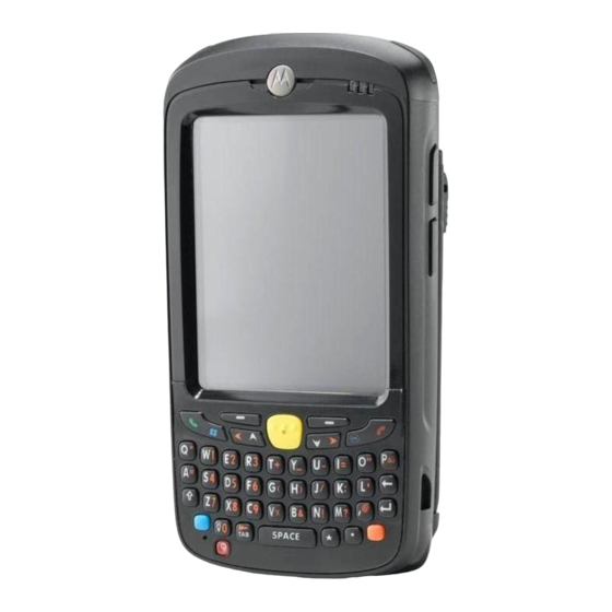
Motorola MC55 Integrator Manual
Enterprise digital assistant
Hide thumbs
Also See for MC55:
- User manual (245 pages) ,
- Accessories manual (6 pages) ,
- Quick start manual (2 pages)
Table of Contents
Advertisement
Quick Links
Advertisement
Table of Contents
Troubleshooting

Related Manuals for Motorola MC55


Summary of Contents for Motorola MC55
- Page 1 MC55 Enterprise Digital Assistant Integrator Guide...
- Page 3 MC55 Enterprise Digital Assistant Integrator Guide 72E-108861-02 Rev. A March 2009...
-
Page 4: Patents
Motorola. No right to copy a licensed program in whole or in part is granted, except as permitted under copyright law. The user shall not modify, merge, or incorporate any form or portion of a licensed program with other program material, create a derivative work from a licensed program, or use a licensed program in a network without written permission from Motorola. -
Page 5: Revision History
Revision History Changes to the original manual are listed below: Change Date Description -01 Rev. A 11/20/08 Initial release. -02 Rev. A 03/06/09 Add MC5574 configuration support. - Page 6 MC55 Integrator Guide...
-
Page 7: Table Of Contents
Charging the Battery ........................1-5 Charging the Main Battery ....................... 1-5 Charging Spare Batteries ......................1-6 Charging Temperature ......................1-6 Powering On the MC55 ........................1-6 Calibrating the Screen ........................1-6 Resetting the MC55 ..........................1-6 Performing a Warm Boot ....................... 1-6 Performing a Cold Boot ........................ - Page 8 Chapter 2: Accessories Introduction ............................2-1 Single Slot USB Cradle ........................2-2 Setup .............................. 2-2 Charging the MC55 Battery ......................2-2 Charging the Spare Battery ......................2-4 Battery Charging Indicators ......................2-4 Charging Temperature ......................2-4 Four Slot Ethernet Cradle ........................2-6 Setup ..............................
- Page 9 Table of Contents Chapter 3: ActiveSync Introduction ............................3-1 Installing ActiveSync ..........................3-1 Mobile Computer Setup ........................3-2 Setting Up an ActiveSync Connection on the Host Computer ............. 3-3 Synchronization with a Windows Mobile 6.1 Device ..............3-4 Chapter 4: Application Deployment Introduction ............................
- Page 10 Service Provider Name Display ......................6-15 SMS Cell Broadcast ..........................6-16 Chapter 7: Maintenance & Troubleshooting Introduction ............................7-1 Maintaining the MC55 .......................... 7-1 Battery Safety Guidelines ........................7-2 Cleaning ............................... 7-3 Materials Required ......................... 7-3 Cleaning the MC55 ........................7-3 Housing ............................
- Page 11 Table of Contents MC55 External Connector Pin-Outs ....................A-6 MC55 Accessory Specifications ......................A-7 Single Slot USB Cradle ........................A-7 Four Slot Battery Charger Cradle ....................A-7 Four Slot Charge Only Cradle ......................A-8 Four Slot Ethernet Cradle ......................A-8 Vehicle Cradle ..........................
- Page 12 MC55 Integrator Guide...
-
Page 13: About This Guide
Screens and windows pictured in this guide are samples and can differ from actual screens. Documentation Set The documentation for the MC55 is divided into guides that provide information for specific user needs. • MC55 Quick Start Guide - describes how to get the MC55 up and running. -
Page 14: Configurations
MC55 Integrator Guide Configurations This guide covers the following configurations: Operating Configuration Radios Display Memory Data Capture Keypads System MC5574 WLAN: 802.11 b/g 3.5” QVGA 128 MB RAM/ 1D laser scanner, Windows Numeric, WPAN: Bluetooth 2.0 Color 256 MB Flash 2D imager, Mobile 6.1... - Page 15 About This Guide xiii OEM Version To determine the OEM software version: > > tab > icon > tab. Start Settings System System Information System 01.15.0000 BTExplorer Software To determine the BTExplorer software version: icon > > > BTExplorer Show BTExplorer File About BTExplorer icon...
-
Page 16: Chapter Descriptions
MC55 configurations and accessories, charging the battery, and resetting the device. • Chapter 2, Accessories describes the accessories available for the MC55 and how to set up power connections and battery charging capabilities, where applicable. • Chapter 3, ActiveSync provides instructions on installing ActiveSync and setting up a partnership between the MC55 and a host computer. -
Page 17: Notational Conventions
MC55, and provides troubleshooting solutions for potential problems during MC55 operation. • Appendix A, Technical Specifications includes tables listing the technical specifications for the MC55 and its accessories. • Appendix B, Bluetooth Configuration includes registry settings required for configuring the use of the Bluetooth stack. -
Page 18: Service Information
Software type and version number. Manufacturing label Motorola responds to calls by e-mail, telephone or fax within the time limits set forth in support agreements. If your problem cannot be solved by Motorola Enterprise Mobility Support, you may need to return your equipment for servicing and will be given specific directions. -
Page 19: Chapter 1: Getting Started
Inspect the equipment. If any equipment is missing or damaged, contact the Motorola Enterprise Mobility support immediately. See Service Information on page xvi for contact information. Prior to using the MC55 for the first time, remove the protective shipping film that covers the scan window, display and camera window. -
Page 20: Installing A Microsd Card
• Charge the MC55. • Power on the MC55. Installing a microSD Card The microSD card slot provides secondary non-volatile storage. The slot is located under the battery pack. Refer to the documentation provided with the card for more information, and follow the manufacturer’s recommendations for use. -
Page 21: Installing The Sim Card
• Information regarding service access and preferences. • Contact information, which can be moved to Contacts on the MC55. • Any additional services to which you have subscribed. NOTE For more information about SIM cards, refer to the service provider's documentation. -
Page 22: Installing The Battery
Close the rubber access door. Install the battery. Installing the Battery NOTE The MC55 ships with either a 2400 mAh or 3600 mAh battery. The 2400 mAh battery is shown in this installation procedure. To install the battery. Insert the battery, bottom first, into the battery compartment in the back of the MC55. -
Page 23: Charging The Battery
Ensure that you follow the guidelines for battery safety described in Battery Safety Guidelines on page 7-2. Charging the Main Battery Before using the MC55 for the first time, charge the main battery until the amber Charging/Battery Status LED remains lit (see Table 1-1 on page 1-5 for charge status indications). -
Page 24: Charging Spare Batteries
A cold boot also restarts the MC55, and also initializes some drivers. Data saved in flash memory or a memory card is not lost. If the MC55 is not functioning properly, perform a warm boot first. If the MC55 still does not respond, perform a cold boot. -
Page 25: Performing A Cold Boot
A clean boot should only be performed by an authorized system administrator. You must connect the CAUTION MC55 to AC power during a clean boot. Removing AC power from the MC55 during a clean boot may render the MC55 inoperable. A clean boot resets the to the factory default settings. All data in the folder is retained. -
Page 26: Waking The Mc55
Perform a cold boot. Immediately, as soon as the device starts to boot and before the splash screen is visible, press and hold the left scan button. Insert the MC55 into a powered cradle. The MC55 updates and then re-boots. Calibrate the screen. -
Page 27: Chapter 2 Accessories
• Cables • Auto Charge Cable - Plugs into a vehicle cigarette lighter to charge the MC55 while on the road. • Charge Only Cable - Provides power to the MC55. • USB Charging Cable - Provides power to the MC55 and USB communication with a host computer. -
Page 28: Single Slot Usb Cradle
2 - 2 MC55 Integrator Guide Single Slot USB Cradle This section describes how to set up and use a Single Slot USB cradle with the MC55. For USB communication setup procedures see Chapter 3, ActiveSync. The Single Slot USB cradle: •... - Page 29 Accessories 2 - 3 Charge Status LED MC55 Battery Charging Figure 2-2...
-
Page 30: Charging The Spare Battery
Charge batteries in temperatures from 0°C to 40°C (32°F to 104°F). Charging is intelligently controlled by the MC55. To accomplish this, for small periods of time, the MC55 or accessory alternately enables and disables battery charging to keep the battery at acceptable temperatures. The MC55 or accessory indicates when charging is disabled due to abnormal temperatures via its LED. - Page 31 Accessories 2 - 5 Spare Battery LED Charging Indicators (Continued) Table 2-1 Spare Battery LED Indication (on cradle) Solid Amber Spare battery is fully charged. Fast Blinking Amber Charging error. Not charging.
-
Page 32: Four Slot Ethernet Cradle
2 - 6 MC55 Integrator Guide Four Slot Ethernet Cradle This section describes how to set up and use a Four Slot Ethernet cradle with the MC55. The Four Slot Ethernet cradle: • Provides 5.4 VDC power for operating the MC55. -
Page 33: Ethernet Cradle Drivers
Daisychaining Four Slot Ethernet Cradles Figure 2-5 Ethernet Cradle Drivers The MC55 includes Ethernet cradle drivers that initiate automatically when you place the MC55 in a properly connected Four Slot Ethernet cradle. After inserting the MC55, configure the Ethernet connection: >... - Page 34 2 - 8 MC55 Integrator Guide IP Address Tab Figure 2-7 In the window, select the appropriate radio button: IP address • Use server-assigned IP address • . Enter the IP address, Subnet mask, and Default gateway, as needed. Use specific IP address Tap the tab.
-
Page 35: Charging And Communication
Charge batteries in temperatures from 0°C to 40°C (32°F to 104°F). Charging is intelligently controlled by the MC55. To accomplish this, for small periods of time, the MC55 alternately enables and disables battery charging to keep the battery at acceptable temperatures. The MC55 indicates when charging is disabled due to abnormal temperatures via its LED. -
Page 36: Four Slot Charge Only Cradle
2 - 10 MC55 Integrator Guide Four Slot Charge Only Cradle This section describes how to set up and use a Four Slot Charge Only cradle with the MC55. The Four Slot Charge Only cradle: • Provides 5.4 VDC power for operating the MC55. -
Page 37: Wall Mount Bracket
Accessories 2 - 11 Wall Mount Bracket Use the optional Wall Mount Bracket to mount a four slot cradle to a wall. To attach the Wall Mount Bracket: Use the Wall Mount Bracket as a template and mark the locations of the four mounting screws. NOTE Use fasteners appropriate for the type of wall and the Wall Mount Bracket mounting slots. - Page 38 2 - 12 MC55 Integrator Guide Swing the four slot cradle down onto the mounting bracket and align the mounting screws so that they fit into the screw slots. Wall Mount Bracket Screw Slots Power Supply Well Wall Mount Bracket Figure 2-13 Tighten the mounting screws to secure the four slot cradle to the bracket.
-
Page 39: Vcd5500 Vehicle Cradle
CAUTION with the MC55 display facing up. Never mount the vehicle cradle on the side or upside down or on a wall that can be subject to impact or collision of greater than 40Gs, in accordance with SAE J1455 Section 4.10.3.5... -
Page 40: Power Connection
UL Listed 5A fuse. The fuse protects the vehicle from an electrical short on the power line to the cradle. To use the cradle to charge the MC55 and spare battery, when the vehicle’s ignition is off, connect the cradle to... - Page 41 Connect the power input cable into the power port on the cradle. To see if the cradle has power, insert the MC55. The Charging LED on the MC55 blinks slowly to indicate charging and turns solid amber when the battery is completely charged. See Table 1-1 on page 1-5 for other indications.
-
Page 42: Charging The Mc55 Battery
Motorola, Inc. is not responsible for any loss resulting from the use of the products while driving. Removing the MC55 To remove the MC55, press the release levers on the cradle and pull the MC55 up and out of the cradle. Release Lever Removing the MC55... -
Page 43: Battery Charging Indicators
Charge batteries in temperatures from 0°C to 40°C (32°F to 104°F). Charging is intelligently controlled by the MC55. To accomplish this, for small periods of time, the MC55 alternately enables and disables battery charging to keep the battery at acceptable temperatures. The MC55 indicates when charging is disabled due to abnormal temperatures via its LED. -
Page 44: Four Slot Battery Charger
2 - 18 MC55 Integrator Guide Four Slot Battery Charger This section describes how to use the Four Slot Battery Charger to charge up to four MC55 spare batteries. Spare Battery Charging Connect the charger to a power source. Insert the spare battery into a spare battery charging well and gently press down on the battery to ensure proper contact. - Page 45 Accessories 2 - 19 Spare Battery LED Charging Indicators Table 2-3 Indication No spare battery in slot; spare battery not placed correctly; cradle is not powered. Fast Blinking Amber Error in charging; check placement of spare battery. Slow Blinking Amber Spare battery is charging.
-
Page 46: Cables
Auto Charge cable. USB Charging Cable The USB Charging cable provides the MC55 with operating and charging power when used with the Motorola approved power supply and AC line cord and synchronize information between the MC55 and a host computer. -
Page 47: Auto Charge Cable
If required, connect the cable power input connector to the Motorola approved power source. Slide the bottom of the MC55 into the connector cup end of the cable until the MC55 is firmly seated in the cup. Slide the two locking tabs up until they both lock into position. -
Page 48: Battery Charging Indicators
To remove, slide the two locking tab down and remove the cable from the MC55. Battery Charging Indicators The MC55 amber Charge LED indicates the MC55 battery charging status. The 2400 mAh battery charges in less than four hours and the 3600 mAh battery charges in less than six hours. See... - Page 49 Accessories 2 - 23 To accomplish this, for small periods of time, the MC55 alternately enables and disables battery charging to keep the battery at acceptable temperatures. The MC55 indicates when charging is disabled due to abnormal temperatures via its LED. See Table 1-1 on page 1-5.
-
Page 50: Vehicle Holder
Do not mount the vehicle holder near the driver seat air bag deployment area. • Do not place the MC55 on top of the dashboard or anywhere without securing it in the vehicle holder. • Do not mount the vehicle holder near the passenger seat air bag deployment area. -
Page 51: Assembly
Windshield Installation Figure 2-25 Flip the lever down to create a vacuum between the suction cup and the mounting surface. Make sure that the suction bond is strong enough before proceeding to the next step. Slide the MC55 into the cradle. -
Page 52: Flat Surface Installation
Locking Tab Insert MC55 into Vehicle Holder Figure 2-26 Connect the auto charger cable to the MC55 and slide the two locking tabs up to secure the cable cup to the MC55. Connect the other end to the cigarette lighter socket. - Page 53 Vehicle Holder Mounted on Flat Surface Figure 2-28 Connect the auto charger cable to the MC55 and slide the two locking tabs up to secure the cable cup to the MC55. Connect the other end to the cigarette lighter socket.
- Page 54 2 - 28 MC55 Integrator Guide...
-
Page 55: Chapter 3 Activesync
Chapter 3 ActiveSync Introduction To communicate with various host devices, install Microsoft ActiveSync (version 4.5 or higher) on the host computer. Use ActiveSync to synchronize information on the mobile computer with information on the host computer. Changes made on the mobile computer or host computer appear in both places after synchronization. NOTE When a mobile computer with Windows Mobile 6.1 is connected to a host computer and an ActiveSync connection is made, the WLAN radio (if applicable) is disabled. -
Page 56: Mobile Computer Setup
3 - 2 MC55 Integrator Guide Mobile Computer Setup NOTE Microsoft recommends installing ActiveSync on the host computer before connecting the mobile computer. The mobile computer by default is set up to communicate through a USB connection. Chapter 2, Accessories provides the accessory setup and cable connection information for use with the mobile computer. -
Page 57: Setting Up An Activesync Connection On The Host Computer
ActiveSync 3 - 3 Setting Up an ActiveSync Connection on the Host Computer To start ActiveSync: Select > > on the host computer. The Window displays. Start Programs Microsoft ActiveSync ActiveSync ActiveSync Window Figure 3-2 NOTE Assign each mobile computer a unique device name. Do not try to synchronize more than one mobile computer to the same name. -
Page 58: Synchronization With A Windows Mobile 6.1 Device
3 - 4 MC55 Integrator Guide Synchronization with a Windows Mobile 6.1 Device NOTE When a mobile computer with Windows Mobile 6.1 is connected to a host computer and an ActiveSync connection is made, the WLAN radio (if applicable) is disabled. This is a Microsoft security feature to prevent connection to two networks at the same time. - Page 59 ActiveSync 3 - 5 Synchronization Option Window Figure 3-6 Select the appropriate settings and click Next Wizard Complete Window Figure 3-7 Click Finish ActiveSync Connected Window Figure 3-8...
- Page 60 3 - 6 MC55 Integrator Guide During the first synchronization, information stored on the mobile computer is copied to the host computer. When the copy is complete and all data is synchronized, the mobile computer can be disconnect from the host computer.
-
Page 61: Chapter 4 Application Deployment
MC55. Security The MC55 implements a set of security policies that determine whether an application is allowed to run and, if allowed, with what level of trust. To develop an application, you must know the security configuration of the device, and how to sign an application with the appropriate certificate to allow the application to run (and to run with the needed level of trust). -
Page 62: Locking Down A Mobile Computer
4 - 2 MC75 Integrator Guide This means that only applications signed with a certificate from the Privileged Execution Trust Certificate Store can run. To support the broadest number of deployments, third-party software developers should perform the following when releasing software for a Windows Mobile 6 devices: •... -
Page 63: Installing Certificates
The Remote API (RAPI) enables applications that run on a desktop to perform actions on a remote device. RAPI provides the ability to manipulate the file system on the remote device, including the creation and deletion of files and directories. By default, Motorola ships with RAPI in the restricted mode. Certain tools, such as RAPIConfig,... -
Page 64: Packaging
Packaging combines an application's executable files into a single file, called a package. This makes it easier to deploy and install an application to the MC55. Package new applications and updates, such as new DLL files, as CAB files, then deploy them to devices. Refer to the Microsoft Windows Mobile 6 Help file for information on CAB files. -
Page 65: Installation Using Airbeam
AirBEAM Smart client. MSP 3.2 The MSP 3 Client Software is a set of software components that come pre-installed on the MC55. The MSP 3 Client software consists of the following components: The RD Client provides support for MSP 3 Staging functionality, provides support for the MSP 3 Legacy Staging process, and provides support for backward-compatible legacy MSP 2.x Legacy Staging functionality. -
Page 66: Microsd Card
The calibration screen appears. Creating a Splash Screen Use a bitmap file to create a customized splash screens for the MC55. Use Image Update with a bitmap file, rather than a package file, to update the splash screen. To create a custom splash screen: Create a .bmp file using a graphic program with the following specifications:... -
Page 67: Xml Provisioning
XML Provisioning To configure the settings on an MC55, use XML provisioning. To install an XML provisioning file on the MC55, create a Cabinet Provisioning File (CPF). A CPF file is similar to a CAB file and contains just one file: _setup.xml. -
Page 68: Regmerge
4 - 8 MC75 Integrator Guide RegMerge RegMerge.dll is a built-in driver that allows updating the registry during a clean boot. RegMerge runs very early in the boot process and looks for registry files (.reg files) in certain Flash File System folders (i.e., \Application) during a clean boot. -
Page 69: Storage
The MC55 uses the Cache Disk for temporary data that can be restored from other sources, for example, for temporarily “caching” HTML web pages by a browser or generating formatted files to send to a printer. Both situations benefit from the increased speed of the cache disk, but you can restore the data if needed. -
Page 70: Persistent Storage
Windows Mobile 6 protects all data and applications from power-related loss. Because Windows Mobile 6 mounts the entire file system and registry in persistent storage (rather than using RAM), MC55 devices provide a reliable storage platform even in the absence of battery power. -
Page 71: Chapter 5 Wireless Applications
Wireless Local Area Networks (WLANs) allow mobile computers to communicate wirelessly and send captured data to a host device in real time. Before using the MC55 on a WLAN, the facility must be set up with the required hardware to run the wireless LAN and the MC55 must be configured. Refer to the documentation provided with the access points (APs) for instructions on setting up the hardware. -
Page 72: Signal Strength Icon
5 - 2 MC55 Integrator Guide Wireless Applications Menu Figure 5-1 Signal Strength Icon The Signal Strength icon in the task tray indicates the MC55’s wireless signal strength as follows: Signal Strength Icons Descriptions Table 5-1 Icon Status Action Excellent signal strength Wireless LAN network is ready to use. -
Page 73: Turning The Wlan Radio On And Off
Wireless Applications 5 - 3 Turning the WLAN Radio On and Off To turn off the WLAN radio tap the Signal Strength icon and select Disable Radio. Disable Radio Figure 5-2 To turn on the WLAN radio tap the Signal Strength icon and select Enable Radio. Enable Radio Figure 5-3... - Page 74 5 - 4 MC55 Integrator Guide...
-
Page 75: Chapter 6 Mc5574 - Gsm Configuration
ID, depending on the type of service. Also use the integrated phone as a modem to connect the MC55 to an ISP or work network. The GSM enabled MC55 can connect to the Internet or work network using Cellular Line, or using the modem specified by the mobile phone service provider. -
Page 76: Mc5574 Service Verification
MC5574 phone and data services require a live SIM card, obtained from a service provider, installed in the MC55 phone. The SIM card has embedded circuitry on one side of its surface which, when inserted into an MC55 phone, provides phone service. The SIM card provides a phone number, determines the features or services available to the subscriber, and identifies the subscriber to the network. -
Page 77: Configuring A Data Connection
MC5574 - GSM Configuration 6 - 3 Phone Settings Window - Network Tab Figure 6-2 Ensure the service provider’s network appears in the Current network: field. If the network does not appear, tap Find Network. If the network still does not appear, verify that the SIM card was installed correctly. - Page 78 6 - 4 MC55 Integrator Guide Connections Window - Make New Connection Figure 6-4 Enter a connection name in the Enter a name for the connection: text box. Select Cellular Line (GPRS) from the Select a modem: drop-down list. Tap Next.
- Page 79 MC5574 - GSM Configuration 6 - 5 Enter a username in the User name text box, if required by the service provider. Enter a password in the Password text box, if required by the service provider. Enter a domain name in the Domain text box, if required by the service provider. Tap Finish.
-
Page 80: Mc5574 Settings
Phone Number automatically displays on the Phone tab when a live SIM card is installed. Select a ring type from the Ring type: drop-down list. The ring type changes the way the MC55 rings when you receive an incoming call. Regardless of the ring type selected, a dialog box appears on the MC55’s display for incoming calls. -
Page 81: Security Tab
MC5574 - GSM Configuration 6 - 7 Security Tab Enabling a PIN NOTE Place emergency calls at any time, without requiring a PIN or a SIM card Security Tab Figure 6-8 To require a PIN when using the phone: From the Security tab, select the Require PIN when phone is used check box under PIN Security. Enter PIN Figure 6-9 Use the touch keypad to enter a four to eight digit PIN. -
Page 82: Services
Tap Start > Settings > Personal tab > Phone icon > Services tab. Start > Phone > Menu > Options > Services tab. MC55 Phone Window - Services Tab Figure 6-10 Select a service from the list and tap Get Settings.. -
Page 83: Caller Id
MC5574 - GSM Configuration 6 - 9 Call Barring/Call Blocking Figure 6-11 Caller ID Enable caller ID to reveal the identity of the person making an outgoing call. Select the Everyone radio button to always display the caller ID. Select the No one radio button to prevent the caller’s identity from appearing to others. -
Page 84: Call Waiting
6 - 10 MC55 Integrator Guide • To forward incoming calls to a different phone number based on a specific situation, select one or more of the check boxes under Forward phone calls only if:. • No answer: enter the phone number to receive forwarded calls only when the phone cannot be answered. -
Page 85: Fixed Dialing
Enter PIN2 and tap Done. NOTE PIN2 is buffered in the MC55 for seven minutes after entry and will not be requested again during this period. Should entry of PIN2 be required then the user must either wait for seven minutes to expire or... -
Page 86: Network
The current network remains active until it’s changed, the signal is lost, or the SIM card is changed. The network the MC55 currently uses appears in the Current network: field at the top of the window. Changing Networks Manually Tap Start >... -
Page 87: Setting Preferred Networks
Tap OK. Setting Preferred Networks Set networks in a preferred order of access. Setting preferred networks allows the MC55 to access a second preferred network if the first is unavailable. Tap Start > Settings > Personal tab > Phone icon > Network tab Start >... -
Page 88: Phone Info
Use the Phone Info tab to view hardware and software information about the phone. Tap Start > Settings > Personal tab > Phone icon > Phone Info tab Start > Phone > Menu > Options > Phone Info tab. MC55 Phone Window - Phone Info Tab Figure 6-23 Tap ok to exit settings. -
Page 89: Network Time Synchronization
MC5574 - GSM Configuration 6 - 15 Network Time Synchronization The MC55 can be configured to synchronize the clock with the time from the carrier network. A registry key on the MC55 has to be created to enable this feature. -
Page 90: Sms Cell Broadcast
- Display both provider and service provider name SMS Cell Broadcast The MC55 can be configured to receive SMS Cell Broadcast messages from the carrier network. Registry keys on the MC55 have to be modified to enable and control this feature. -
Page 91: Chapter 7 Maintenance & Troubleshooting
Do not store or use the MC55 in any location that is dusty, damp, or wet. • Use a soft lens cloth to clean the MC55. If the surface of the MC55 screen becomes soiled, clean it with a soft cloth moistened with a diluted window-cleaning solution. -
Page 92: Battery Safety Guidelines
MC55 Integrator Guide • A screen protector is applied to the MC55. Motorola recommends using this to minimize wear and tear. Screen protectors enhance the usability and durability of touch screen displays. Benefits include: • Protection from scratches and gouges •... -
Page 93: Cleaning
Always wear eye protection. Read warning label on compressed air and alcohol product before using. If you have to use any other solution for medical reasons please contact Motorola for more information. WARNING Avoid exposing this product to contact with hot oil or other flammable liquids. If such exposure occurs, unplug the device and clean the product immediately in accordance with these guidelines. -
Page 94: Cleaning Cradle Connectors
Ensure battery is installed properly. See Installing the Battery on not installed page 1-4. properly. System crash. Perform a warm boot. If the MC55 still does not turn on, perform a cold boot. See Resetting the MC55 on page 1-6. - Page 95 MC55 shuts off. MC55 is inactive. The MC55 turns off after a period of inactivity. If the MC55 is running on battery power, set this period from 1 to 5 minutes, in one-minute intervals. If the MC55 is running on external power, set this period to 1, 2, 5, 10, 15, or 30 minutes.
- Page 96 Refer to the EMDK or Control Panel application. bar code. MC55 is not If the MC55 does not beep on a good decode, set the application programmed to to generate a beep on good decode. generate a beep.
-
Page 97: Bluetooth Connection
MC55 or power. cradle and to AC power. spare battery is MC55 is not seated Remove and re-insert the MC55 into the cradle, ensuring it inserted. firmly in the cradle. is firmly seated. Spare battery is not Remove and re-insert the spare battery into the charging seated firmly in the slot, ensuring it is firmly seated. -
Page 98: Four Slot Ethernet Cradle
Symptom Cause Solution Battery is not Battery was removed Replace the MC55 in the cradle. The 2400 mAh battery fully charging. from the charger or charges in approximately four hours and the 3600 mAh charger was unplugged battery charges in approximately six hours. Tap Start >... -
Page 99: Vehicle Cradle
Perform setup as described in Chapter 3, ActiveSync. improperly configured. MC55 ActiveSync On the MC55, tap Start > ActiveSync > Tools > Options > disabled or not Options button. Then, uncheck the Enable PC sync using configured to accept this connection: check box. -
Page 100: Four Slot Spare Battery Charger
Battery is faulty. Verify that other batteries charge properly. If so, replace the faulty battery. The MC55 is not fully Detach and re-attach the power cable to the MC55, ensuring it is attached to power. firmly connected. - Page 101 Symptom Possible Cause Action During data Cable was Re-attach the cable and retransmit. communication, disconnected from no data MC55 during transmits, or communications. transmitted data Incorrect cable See the system administrator. configuration. incomplete. Communication Perform setup as described in the Chapter 3, ActiveSync.
- Page 102 7 - 12 MC55 Integrator Guide...
-
Page 103: Appendix A Technical Specifications
Appendix A Technical Specifications MC55 Technical Specifications The following table summarizes the MC55’s intended operating environment and technical hardware specifications. MC55 EDA Technical Specifications Table A-1 Item Description Physical Characteristics Dimensions MC5574: Height: 15.2 cm (6.0 in.) Width: 7.7 cm (3.03 in.) Depth: 2.7 cm (1.10 in.) - Page 104 A - 2 MC55 Integrator Guide MC55 EDA Technical Specifications (Continued) Table A-1 Item Description Expansion Slot User accessible microSD slot. Network Connections High-speed USB, host or client, Bluetooth and WiFi. USB host mode available with custom cables only. Notification...
- Page 105 Technical Specifications A - 3 MC55 EDA Technical Specifications (Continued) Table A-1 Item Description Wireless LAN Data and Voice Communications Wireless Local Area Network ® MC5574: Dual-mode IEEE 802.11b/g (WLAN) radio ® MC5590: Tri-mode IEEE 802.11a/b/g Data Rates Supported 1, 2, 5.5, 6, 9, 11, 12, 18, 24, 36, 48, and 54 Mbps Operating Channels MC5574: Chan 1-13 (2412-2472 MHz), Chan 14 (2484 MHz) Japan only;...
- Page 106 A - 4 MC55 Integrator Guide MC55 EDA Technical Specifications (Continued) Table A-1 Item Description Wireless Wide Area Network Quad Band GSM/ EDGE Global: 3GPP TS 51.010, GCF approved module USA: FCC Part 22, Part 24 Canada: RSS-132, RSS-133 EU: EN301 511 Australia: AS/ACIF S024.1 &...
- Page 107 Technical Specifications A - 5 MC55 EDA Technical Specifications (Continued) Table A-1 Item Description Optical Resolution 640 H x 480 V pixels (gray scale) Roll 360° Pitch Angle +/- 60° from normal Skew Tolerance +/- 50° from normal Ambient Light Total darkness to 9,000 ft.
-
Page 108: Mc55 External Connector Pin-Outs
A - 6 MC55 Integrator Guide MC55 External Connector Pin-Outs Pin 1 External Connector Figure A-1 External Connector Pin-Outs Table A-2 Description External Trigger/Cradle Detect USB_ID 5.4 VDC USB_VCC USB_D- USB_D+ Ground... -
Page 109: Single Slot Usb Cradle
Technical Specifications A - 7 MC55 Accessory Specifications Single Slot USB Cradle Single Slot USB Cradle Technical Specifications Table A-3 Feature Description Dimensions Height: 7.1 cm (2.80 in.) Width: 11.0 cm (4.33 in.) Depth: 15.0 cm (5.91 in.) Weight 210 g (7.41 oz) -
Page 110: Four Slot Charge Only Cradle
A - 8 MC55 Integrator Guide Four Slot Battery Charger Technical Specifications (Continued) Table A-4 Feature Description Humidity 5% to 95% non-condensing Drop 76.2 cm (30.0 in.) drops to vinyl tiled concrete at room temperature Electrostatic Discharge (ESD) +/- 15 kV air... -
Page 111: Vehicle Cradle
Technical Specifications A - 9 Four Slot Ethernet Cradle Technical Specifications (Continued) Table A-6 Feature Description Operating Temperature 0°C to 50°C (32°F to 122°F) Storage Temperature -40°C to 70°C (-40°F to 158°F) Charging Temperature 0°C to 40°C (32°F to 104°F) Humidity 5% to 95% non-condensing Drop... -
Page 112: Cables
A - 10 MC55 Integrator Guide Cables USB Charging Cable Technical Specifications Table A-8 Feature Description Length 161.9 cm (63.74 in.) Operating Temperature -10°C to 50°C (14°F to 122°F) Storage Temperature -40°C to 70°C (-40°F to 158°F) Humidity 10% to 95% non-condensing... -
Page 113: Appendix B Bluetooth Configuration
Bluetooth stack can be used at a time. By default, the StoneStreet One Bluetooth stack is enabled. A registry key on the MC55 can be modified to disable the StoneStreet One stack and enable the Microsoft stack. Using a registry editor, navigate to the following:... - Page 114 B - 2 MC55 User Guide...
- Page 115 Glossary ActiveSync. ActiveSync is a data synchronization program developed by Microsoft for use with Windows Mobile operating systems. AFH. Adaptive Frequency Hopping AKU. (Adaptation Kit Update) Updates to the Windows Mobile operating system. API. (Application Programming Interface) An interface by means of which one software component communicates with or controls another.
- Page 116 Glossary - 2 MC55 Integrator Guide bps. See Bits Per Second. Byte. On an addressable boundary, eight adjacent binary digits (0 and 1) combined in a pattern to represent a specific character or numeric value. Bits are numbered from the right, 0 through 7, with bit 0 the low-order bit. One byte in memory is used to store one ASCII character.
- Page 117 Depth of Field. The range between minimum and maximum distances at which a scanner can read a symbol with a certain minimum element width. Device Configuration Package. The Motorola Device Configuration Package provides the Product Reference Guide (PRG), flash partitions, Terminal Configuration Manager (TCM) and the associated TCM scripts. With this package hex images that represent flash partitions can be created and downloaded to the mobile computer.
- Page 118 IEEE Address. See MAC Address. Input/Output Ports. I/O ports are primarily dedicated to passing information into or out of the terminal’s memory. MC55 mobile computers include USB ports. Interleaved 2 of 5. A binary bar code symbology representing character pairs in groups of five bars and five interleaved spaces.
- Page 119 Mobile Computer. In this text, mobile computer refers to the MC55. It can be set up to run as a stand-alone device, or it can be set up to communicate with a network, using wireless radio technology.
- Page 120 Glossary - 6 MC55 Integrator Guide NVM. Non-Volatile Memory. Open System Authentication. Open System authentication is a null authentication algorithm. PAN . Personal Area Network. Using Bluetooth wireless technology, PANs enable devices to communicate wirelessly. Generally, a wireless PAN consists of a dynamic group of less than 255 devices that communicate within about a 33-foot range.
- Page 121 Glossary - 7 SDK. Software Development Kit Shared Key. Shared Key authentication is an algorithm where both the AP and the MU share an authentication key. SID. System Identification code. An identifier issued by the FCC for each market. It is also broadcast by the cellular carriers to allow cellular devices to distinguish between the home and roaming service.
- Page 122 Glossary - 8 MC55 Integrator Guide Terminal. See Mobile Computer. Terminal Emulation. A “terminal emulation” emulates a character-based mainframe session on a remote non-mainframe terminal, including all display features, commands and function keys. The VC5000 Series supports Terminal Emulations in 3270, 5250 and VT220.
- Page 123 Index spare ....... . . 2-18 vehicle cradle ......2-16 accessories bluetooth cables .
- Page 124 Index - 2 MC55 Integrator Guide vehicle cradle ......2-16 charging temperature ......1-6 flash file system clean boot .
- Page 125 Index - 3 hard ....... 1-6, 1-7 soft ........1-6 keypads .
- Page 126 Index - 4 MC55 Integrator Guide stylus ........1-1 subscriber identification module .
- Page 128 1-800-927-9626 http://www.motorola.com/enterprisemobility MOTOROLA and the Stylized M Logo and Symbol and the Symbol logo are registered in the U.S. Patent and Trademark Office. All other product or service names are the property of their registered owners. © Motorola, Inc. 2009...
Need help?
Do you have a question about the MC55 and is the answer not in the manual?
Questions and answers