Table of Contents
Advertisement
Advertisement
Table of Contents

Related Manuals for Nikon SMZ1000


Summary of Contents for Nikon SMZ1000
- Page 1 M248 E 06.2.NF.3 Stereoscopic Zoom Microscope SMZ1000 / SMZ800 Instructions...
-
Page 3: Warning/Caution Symbols Used In This Manual
Thank you for purchasing the Nikon product. This instruction manual is written for the users of Nikon Stereoscopic Zoom Microscopes. To ensure correct usage, read this manual carefully before operating the instrument. • It is prohibited to reproduce or transmit this manual in part or whole without Nikon’s expressed permission. -
Page 4: Be Sure To Always Follow These Guidelines
2. Do not disassemble Disassembly may result in damage to the instrument. Never disassemble any part except as described in this operation manual. Contact your Nikon representative if you notice any malfunction of this instrument. 3. Check the input voltage... -
Page 5: Caution
CAUTION 1. Caution when replacing lamps The lamp and the surrounding area become very hot during and immediately after using the illuminator. Be careful not to burn yourself. In addition, when replacing a lamp be sure the lamp has cooled sufficiently. 2. - Page 6 1. Installation location Note the following points when installing the stereoscopic microscope. • Install the microscope in a location with the temperature between 0° and 40°C, and humidity of less than 80%. If installed in a hot and humid location, mold may form on the lenses or condensation may occur inside, resulting in reduced performance or damage to the microscope.
- Page 7 During storage, place a plastic cover over the equipment to prevent dust accumulation. 6. Regular inspections Regular inspections are recommended in order to maintain peak performance. Please consult your Nikon representative for details about regular inspections.
-
Page 8: Table Of Contents
Contents Warning/Caution Symbols Used in This Manual ......1 Be sure to always follow these guidelines........2 WARNING ..................2 CAUTION ...................3 Nomenclature ................... 8 Assembly ..................12 Usage ....................15 1 Preparations For Observation ............15 1. Adjust the torque of the focus knob........15 2. - Page 9 5. Lighting area adjustment [G-LS]........... 29 6. Attaching filters [C-DSLS] ............ 29 2 P-ICI2 Coaxial Episcopic Illuminator ......... 29 Photomicrographic and TV-related Accessories ....32 1. Photomicrographic magnification ......... 33 2. Attaching the beam splitter ............ 33 3. Photo reticles ................. 34 4.
-
Page 10: I Nomenclature
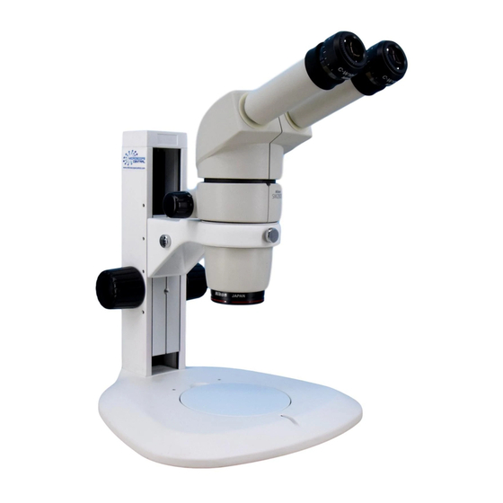
Nomenclature The figures on p.8 & 9 show a SMZ1000 zooming body, with P-BT binocular eyepiece tube, C-W 10X eyepieces, Plan Apo 1X objective, C-FMC focusing mount, and C-PS160 plain stand. Eyepiece sleeve Diopter ring Refer to “Adjust the P-BT Binocular diopter”... - Page 11 Zooming knob clicks ON/OFF screw (inside) Refer to “ON/OFF of the Zooming Knob Clicks” on p.17. Clamp tool Used for the stage plate clamp screw, eyepiece tube clamp screw, etc. Same size as the small hexagonal wrench supplied with the zooming body. Stored in the top of the pillar.
- Page 12 The illustrations on p.10 & 11 show a SMZ800 zooming body, with P-BT binocular eyepiece tube, C-W 10X eyepieces, Plan 1X objective, and C-PS plain focusing stand. Eyepiece sleeve Diopter ring Refer to “Adjust the diopter” on p.16. P-BT Binocular eyepiece tube Eyepiece P-BTL low eye-level...
- Page 13 Nomenclature Zooming knob clicks ON/OFF screw (inside) Refer to “ON/OFF of the Zooming Knob Clicks” on p.17. Hexagonal wrench hanger Holds the supplied hexagonal wrenches. Hexagonal wrench (Large) Supplied with the focusing stand. Screw hole for mounting an Used for changing Epi-arm for halogen illuminator.
-
Page 14: Assembly
Assembly ☞ • An equipment model name in the bold-faced brackets [ ] indicates that the following description is exclusively for that model. [C-PS160] Pillar Attach the pillar to the stand. Insert the pillar straight into the stand with the Groove groove of the pillar located down as far as the pillar reaches to the bottom. - Page 15 [C-PS & C-PSC] The stand arm can be lowered. (If you Groove do not need to lower the arm, jump to step 6.) Use the hexagonal wrench (large - supplied with the focusing stand) to loosen the arm fixing screw. Reattach the arm using the screw hole at the lower side of the vertical slider.
- Page 16 Assembly Insert the eyepieces into the eyepiece sleeves. Be sure that it is inserted all the way until it touches the end of the sleeve. Note) When inserting the eyepiece, hold the rubber cover of the eyepiece. Holding the diopter ring causes a failure. Especially, be careful with the 10X eyepieces because their rubber covers obstruct the view of the sleeve end.
-
Page 17: Usage
Usage Preparations For Observation Adjust the torque of the focus knob. Adjust the torque of the focus knob so as not to fall down the zooming body on its own weight. [C-FMC] Increasing the torque. Turn the torque adjustment ring using the clamp tool. -
Page 18: Adjust The Diopter
Adjust the diopter. This adjustment should be performed every time the observer is changed since the eyesight differs between individuals. 1 Turn the diopter rings on both eyepieces to set them at the 0 position (match the 0 line with the index line). 2 Turn the zooming knob to the highest magnification. -
Page 19: Zoom
Usage Zoom Change the zooming magnification. Turning the zooming knobs on the left and right side of the zooming body will change the magnification of the sample image. ■ Total Magnification The zooming knob has the indication of the zooming magnification. The total magnification can be found by multiplying the magnification of the objective times that of the eyepieces. -
Page 20: If You Cannot Focus On The Sample Though The Zooming Body Is At The Highest Position
Wrong [C-PS & C-PSC] Use the C-ER auxiliary adapter available as an option. (This adapter can’t be used for the Auxiliary SMZ1000.) adapter ☞ • Refer to the Table 2 on p.38 for the sample heights which may be viewed. -
Page 21: Using Accessories
Using Accessories Reticles Your reticles may be attached to the eyepiece. Once remove the field ring (or lens room of the 20X and 30X) from the eyepiece. Attach the reticle with its pattern surface facing down to the eyepiece and reattach the field ring (or lens room). -
Page 22: P-Berg Tilted Eyepiece Tube
P-BERG tilted eyepiece tube This eyepiece tube allows the angle of the eyepiece sleeve to be continuously adjusted as desired by the observer. It is also possible to change the eye level by rotating the interpupillary distance adjuster (shown in gray in the illustration) 180°. The installation procedure for this eyepiece tube is the same as for the P-BT binocular eyepiece tube. -
Page 23: Plan 1X Ergo Objective
Use the microscope as usual after setting the eye level. Note) When attaching to the SMZ1000, vignetting will occur in the lateral direction of the viewfield at the high eye level with 1X or lower zoom magnification. -
Page 24: Sm-S4L 4 X 4 Stage L
Using Accessories SM-S4L 4 X 4 Stage L SM-S4L 4 X 4 stage L may be attached by Stage 4 X 4 stage clamp screw using the C-4SA stage adapter. In this case, use the C-ER auxiliary adapter or C-EP extension pillar because the position of the sample will become higher. -
Page 25: Illuminator
Illuminator Halogen Illuminators There are two illuminators available: the G-LS of 6V 10W and the C- DSLS of 6V 20W. Note) These illuminators are not adequate to observe the sample having a high reflective surface. Use the P-ICI2 Coaxial Episcopic Illuminator on p.29 for this purpose. -
Page 26: Lamp
Lamp CAUTION The lamp and the surrounding area become very hot during and immediately after using the illuminator. Be careful not to burn yourself. In addition, be sure the lamp has cooled sufficiently before replacing a lamp. Pull the lamp socket from the lamp house and G-LS insert the lamp straight into the socket as far as it will go. -
Page 27: Attaching G-Ls To The Stand [C-Ps & C-Psc]
Illuminator lamp, handle it through a piece of cloth or through its packaging until replacement is complete. If you get fingerprints on the lamp, wipe gently with a piece of clean cloth dampened with alcohol. Attaching G-LS to the stand [C-PS & C-PSC] Set so that the protrusion on the lamp house G-LS aligns with the inside of the screw hole on the... - Page 28 2 Epi arm Clamp knob Slightly loosen the clamp knob on the Simultaneously arm. Screw in the mounting screw at clamps two the end of the Epi arm into the screw arms/joints. hole of the stand (screw hole for Joint mounting an Epi-arm) while turning the joint.
-
Page 29: Power Supplies
Check that the voltage displayed matches the Fuse voltage used in your area. If the voltages do not match, do not use the power supply and Always use the fuse contact your Nikon representative. specified. (Rear view) Power cord Output connector... - Page 30 Power Supply XN A (only for regions with 100/120 V power) Input rating Power supply for 100V regions only: 100 V AC, 50/60 Hz, 30 W Power supply for 120V regions only: 120 V AC, 50/60 Hz, 30 W Output rating 3-6 V AC, 3.3 A Fuse rating 250 V, 1 A...
-
Page 31: Lighting Area Adjustment [G-Ls]
Illuminator Lighting area adjustment [G-LS] It is possible to adjust the lighting area by moving the lamp socket back and forth. Adjust the lighting area to allow easy viewing. Attaching filters [C-DSLS] Rotate and remove the filter cap at the end of the lamp house and insert a filter. - Page 32 table. If the magnification out of the specified range is used, uneven illumination will occur or the seeing of the sample image will be degraded. Mount the P-ICI2 onto the zooming body aligning the groove on the bottom of the P-ICI2 main body with the positioning pin on Groove the zooming body while tilting the P-ICI2...
- Page 33 Illuminator The optical axis of the 1/4 lambda plate is at the 45° position from the red dot. Brightness is the maximum when the red dot is positioned at the front and switches from bright to dark by each 45° position. Adjust the plate to the position where the brightness and contrast are best suited for the Red dot...
-
Page 34: Photomicrographic And Tv-Related Accessories
Photomicrographic and TV-related Accessories It is possible to photograph images or display them on a TV monitor by attaching a beam splitter between the zooming body and the eyepiece tube. There are two beam splitters available: the S2 P-IBSS2 with one port and the D2 P-IBSD2 with two ports. -
Page 35: Photomicrographic Magnification
Photomicrographic and TV-related accessories Photomicrographic magnification Photomicrographic magnification = (PLI projection lens magnification) × (Zoom magnification) × (Objective magnification) • When the P-ICI2 Coaxial Episcopic Illuminator is used: Photomicrographic magnification = (PLI projection lens magnification) × (Zoom magnification) × (Objective magnification) × 1.5 •... -
Page 36: Photo Reticles
Photo reticles Attaching the C-FP photo reticle to the C-W10X eyepiece permits you to make focusing for phtotomicrography through the eyepiece. Select the correct frame indicating the area being photographed according to the magnification of the PLI projection lens. For more accurate focusing and photographing area, use the finder of the photomicrographic equipment. - Page 37 Photomicrographic and TV-related accessories 2 Focusing The following is the focusing procedure using the photo reticle. For the focusing procedure using the finder of the photomicrographic equipment, refer to the instruction manual of the phtotomicrographic equipment. 1 Once remove the field ring of the eyepiece and attach the photo mask reticle.
-
Page 39: Table 1: Total Magnification And Real Field
Table 1: Total Magnification and Real Field... -
Page 40: Table 2: Observable Sample Heights [Mm]
Table 2: Observable Sample Heights Table 2: Observable Sample Heights [mm] SMZ1000 + C-PS160 + C-FMC When using Mount Mount up When using SM-S4L Objectives normal side down C-EP and C-EP position position extension pillar extension pillar Acro 0.5X 0 ~ 24 —...
Need help?
Do you have a question about the SMZ1000 and is the answer not in the manual?
Questions and answers