Table of Contents
Advertisement
INSTRUCTIONS
IX73
RESEARCH INVERTED MICROSCOPE
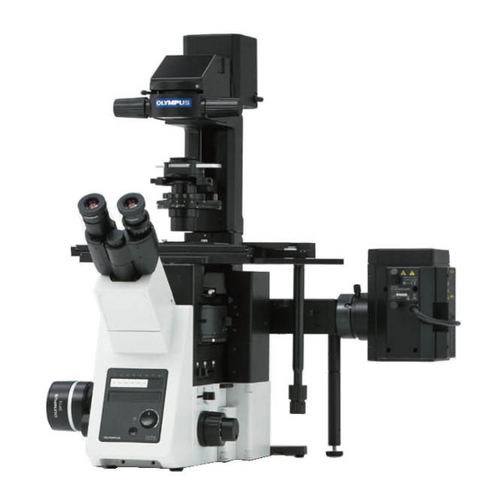
This instruction manual is for the Olympus research inverted microscope model IX73.
To ensure the safety, obtain optimum performance and to familiarize yourself fully with the use
of this microscope, we recommend that you study this manual thoroughly before operating the
microscope.
Retain this instruction manual in an easily accessible place near the work desk for future reference.
A X 8 1 5 7
Advertisement
Table of Contents

Related Manuals for Olympus IX73


Summary of Contents for Olympus IX73
- Page 1 IX73 RESEARCH INVERTED MICROSCOPE This instruction manual is for the Olympus research inverted microscope model IX73. To ensure the safety, obtain optimum performance and to familiarize yourself fully with the use of this microscope, we recommend that you study this manual thoroughly before operating the microscope.
- Page 2 In accordance with European Directive 2002/96/EC on Waste Electrical and Electronic Equip- ment, this symbol indicates that the product must not be disposed of as unsorted municipal waste, but should be collected separately. Refer to your local Olympus distributor in EU for return and/or collection systems available in your country.
-
Page 3: Table Of Contents
IMPORTANT -- Be sure to read this section for safe use of the equipment. -- Intended use .......................................4 Conformity of the System ................................5 Handling Precautions..................................6 Maintenance and Storage ................................6 1 MODULE NOMENCLATURE ....................7 2 NOMENCLATURE ..........................8 3 TRANSMITTED LIGHT BRIGHTFIELD OBSERVATION PROCEDURE .12 4 USING THE CONTROLS ......................14 4-1 Power Supply Unit and Microscope Frame ..................14 Turning Power On, Adjusting the Brightness .........................14... - Page 4 4-4 Observation Tube ..............................23 Adjusting the Interpupillary Distance ............................23 Adjusting the Diopter ...................................23 Using the Eye Shades ..................................24 Mounting the Eyepiece Micrometer Disk ..........................24 Selecting the Light Path of the Trinocular Tube ......................24 Adjusting the Tilt (U-TBI90) ................................24 4-5 Illumination Column (IX3-ILL) ..........................25 Tilting the Illumination Column ..............................25 Mounting Filters......................................26 Using the Field Iris Diaphragm ..............................27...
- Page 5 Attaching the DIC Optical Elements ............................38 Attaching the Analyzer and DIC Slider ..........................39 Attaching the Polarizer (IX-LWPO) ............................40 Cross-Nicol Adjustment ..................................41 Observation Method ....................................42 5-3 Simplified Polarized Light Observation ....................43 Attaching the Analyzer and Polarizer ............................43 Observation Method ....................................43 5-4 Reflected Light Fluorescence Observation (Separate Manual) ........44 5-5 Relief Contrast Observation (Separate Manual) ................44 6 CAMERA RECORDING ......................45 Camera Adapter ......................................45...
- Page 6 Attaching the Stage ....................................55 Attaching the Objectives ..................................57 Attaching the Condenser Refocusing Stopper ......................57 Attaching the Condenser ................................58 Attaching the Observation Tube ..............................59 Attaching the Eyepieces ..................................60 Using the Accessory Mounting Holes ..........................60 Using the Frame Fix Plate (IX3-FP) ................................... 61 Connecting the Cables ..................................62 Cable Distributions ....................................63 Cable Cover .........................................64...
-
Page 7: Releasing The Transport Lock
IX73 IMPORTANT This microscope employs UIS2 optical design. For the applicable modules, please consult Olympus or refer to the latest brochures or Olympus website. Less than optimum performance may result if inappropriate module combinations are used. Configuration of Instruction Manuals Since this microscope is expandable to a variety of systems, separate instruction manuals are prepared so that the user has to read only the manuals according to the user’s own system. -
Page 8: Safety Precautions
SAFETY PRECAUTIONS 1. If potentially infectious samples may be observed, use protective gloves or other protective means to prevent the skin from contacting with samples directly. After observation, be sure to clean the portion contacted with samples. • Moving this device is accompanied with the risk of dropping the samples. - Page 9 25. Always use the power cord provided by Olympus. If no power cord is provided, please select the proper power cord by referring to the section “PROPER SELECTION OF THE POWER CORD” at the end of this instruction manual.
-
Page 10: Intended Use
Positions of caution labels Back side of microscope frame If the caution label becomes dirty or is peeled off, contact Olympus for replacement. Intended use This device has been designed to be used to observe magnified images of specimens in various routine work and research applications. -
Page 11: Conformity Of The System
Remove IX3-AN from the light path before ob- servation. Decks of IX73 The IX73P2F is equipped with two decks, 1st deck (upper deck) and 2nd deck (lower deck), accepting optional acces- sories such as the intermediate magnification changer, mirror unit cassette, etc. -
Page 12: Handling Precautions
Handling Precautions 1. These products are precision instruments. Handle them with care and avoid subjecting them to sudden or severe impact and also connect the cables gently. 2. Do not use the microscope where it is subjected to direct sunlight, high temperature and humidity, dust or vibrations. (For operating conditions, see Chapter 8, “SPECIFICATIONS”... -
Page 13: Module Nomenclature
For information on the modules marked with “*", refer to their instruction manuals. Modules marked # are components of the IX73 motorized system. Also you can configure the IX73 motorized coded system in combination with modules marked #. For details, refer to IX3-CBM instruction manual. -
Page 14: Nomenclature
NOMENCLATURE } If you have not yet assembled the microscope, read Chapter 9, “ASSEMBLY” (pages 50 to 64). Filter pocket (p.26) Condenser height adjustment knob (p.27) Field iris diaphragm lever (p.27) Antiglare plate Diopter adjustment Stage center plate (p.18) ring (p.23) Interpupillary distance adjustment scale (p.23) Light path selector lever (p.15) - Page 15 IX73 Left Side View of Microscope Left side port Fine adjustment knob (p.17) Detachable. Coarse adjustment knob (p.17) Pre-focusing lever (p.17) Other Modules Motorized LWD condenser IX3-LWUCDA Motorized operation button • TURRET : Switches the turret of the condenser • POL...
- Page 16 LWD Universal Condenser UCD-Adapter IX2-LWUCD IX-ADUCD } This is a manually controlled condenser. Condenser height fine Aperture iris adjustment knob diaphragm lever Turret ULWCD Condenser IX-ULWCD } This is a manually controlled condenser. Universal Condenser Aperture iris U-UCD8 Turret diaphragm lever } This is a manually controlled condenser.
-
Page 17: Mechanical Stage
IX73 Plain Stage Mechanical Stage IX2-SP IX-MVR Manipulator mounting screw holes M6 screw (x 6) IX-MVR mounting screw holes (On both sides) Y-axis knob X-axis knob Mechanical stage with right handle IX3-SVR X-axis knob Y-axis knob Halogen Lamp Power Supply Unit... -
Page 18: Transmitted Light Brightfield Observation Procedure
TRANSMITTED LIGHT BRIGHTFIELD OBSERVATION PROCEDURE } The following flow shows the operating procedure for the transmitted light brightfield observation which is the basic observation method of this microscope. The operating procedures for phase contrast observation and DIC observa- tion will be described separately in Chapter 5, “OTHER OBSERVATION METHODS” on page 33. For the fluorescence observation, refer to the separate instruction manual entitled “... - Page 19 IX73 } Make a photocopy of the observation procedure pages and post it near your microscope.
-
Page 20: Using The Controls
When the TH4-HS Hand Switch is Used } The illumination brightness can be adjusted from the hand switch in the same way as on the IX73 microscope. The hand switch is provided with double-sided adhesive tape, so it can be adhered to an easy-to-use position. -
Page 21: Light Path Selection
IX73 Light Path Selection } The light path selector lever allows for light path switching between the observation and left side port paths. Eyepiece / Camera (Left side port) 100% 100% } If acquiring the image by setting the light path as [Eyepiece 50%/ Left side port 50%], the light such as fluorescent lamp may enter from the eyepiece to be reflected in the acquired image. -
Page 22: Dust Tray
Dust tray } This tray prevents dust, etc. from falling into the microscope. Remove and clean it on a regular basis. Rotate the fixing screws (2 pcs.) to remove them. Slide the dust tray to remove it. } Wash the dust tray with water and wipe it with the dry cloth to dry well before attaching it to the microscope. -
Page 23: Focusing Block
IX73 4-2 Focusing Block Rotation Direction of the Coarse/Fine Adjustment Knobs } Rotating the coarse or fine focus adjustment knob toward the front (in the direction of the arrow) raises the objective and toward the rear (opposite direction) lowers the objective. -
Page 24: Stage
4-3 Stage Placing the Specimen Place the specimen on the center of the stage. } If the specimen is prone to slide on the stage, attach the stage clips (IX-SCL) and clamp the specimen down with the clips. With the mechanical stage with right handle IX3-SVR For IX3-SVR, in addition to the holder for the round stage center plate, following sample holders corresponding to each sample can be attached. - Page 25 IX73 IX3-HO35D Place the 35 mm dish on the 35 mm dish fixing holder Tighten the fixing screws (3 screws) placed on the side with the Allen screwdriver provided with IX3-HO35D to secure the 35 mm dish. } The 35 mm dish can be secured easily by tightening the fixing screws after flipping over the 35 mm dish in advance.
- Page 26 With the mechanical stage IX-MVR + stage IX2-SP } 96-well or 24-well microplates, etc. are held in place by the speci- men holder. Microplates with dimensions of max. 136 mm x 92 mm can be ac- commodated in this way. Open the spring-loaded finger of the specimen holder 1 and slide the microplate into the holder frame.
-
Page 27: Moving The Specimen
IX73 Moving the Specimen • Do not attempt to rotate the stage handle forcedly exceeding CAUTION the stage movable range. The stage may be damaged. • As the objective may interfere with the stage depending on the focus position, be sure to operate carefully. -
Page 28: Connecting The Grounding Wire
Stage movable range With movement range limit screw : 50 mm in vertical direction, 50 mm in horizontal direction Without movement range limit screw: 75 mm in vertical direction, 114 mm in horizontal direction When using the center plate provided with IX3-SVR, attach the CAUTION movement range limit screw. -
Page 29: Observation Tube
IX73 4-4 Observation Tube Adjusting the Interpupillary Distance While looking through the eyepieces, adjust the binocular vision until the left and right fields of view coincide completely. The index dot · indicates the interpupillary distance. } Note your interpupillary distance so that it can be quickly duplicated... -
Page 30: Using The Eye Shades
Using the Eye Shades When wearing eyeglasses Use the eye shades in the normal, folded-down position. This will prevent the eyeglasses from being scratched. When not wearing eyeglasses Extend the folded eye shades in the direction of the arrow to prevent extraneous light from entering between the eyepieces and eyes. -
Page 31: Illumination Column (Ix3-Ill)
IX73 4-5 Illumination Column (IX3-ILL) Tilting the Illumination Column } When replacing large specimens, placing a micromanipulator or replacing a patch clamp electrode, working space can be created by tilting the illumination column. Using the Allen screwdriver, turn the column tilt clamping screw to loosen it. -
Page 32: Mounting Filters
Mounting Filters } 45 mm diameter, maximum 6 mm thick filters can be mounted. Vari- ous filters, such as the frost filter Ø45 mm (45FR), color temperature conversion filter (LBD), green interference filter (IF550) and ND filter can be mounted. of the filter holder and lift it. -
Page 33: Using The Field Iris Diaphragm
IX73 Using the Field Iris Diaphragm } The field iris diaphragm lever is used to adjust the diameter of the il- lumination beam in accordance with the objective in use. Adjust the diaphragm so that the field of view is circumscribed by the field iris diaphragm to cut extra light and improve the contrast of images. -
Page 34: Condenser
4-6 Condenser Centering the Condenser With the Condenser (IX3-LWUCDA, IX2- LWUCD, IX-ULWCD or IX2-MLWCD) Rotate the turret (either manually or electrically) to select the “BF” brightfield observation (with which no optical element is engaged in the light path). Move the aperture iris diaphragm lever to open the diaphragm. Move the field iris diaphragm lever to the fully open position Both the right and left... - Page 35 IX73 With the U-UCD8 Condenser Rotate the condenser height fine adjustment knob counterclock- wise to loosen it, then push the knob all the way toward the rear. Rotate the condenser height adjustment knob in the direction of the arrow to lower the condenser to the level not to hit the specimen.
-
Page 36: Using The Aperture Iris Diaphragm
Using the Aperture Iris Diaphragm } In general, the potential resolving power of an objective is fully 70-80% utilized if the diaphragm is stopped down to correspond with the numerical aperture (N.A.) of the objective. 30-20% } Depending on the specimen, image contrast or focal depth in ob- servation or acquisition may be improved by keeping the aperture iris diaphragm stopped down a little. -
Page 37: Oil- Or Water-Immersion Objective
Using Oil- or Water-Immersion Objective } If you use an oil-immersion objective, use immersion oil as de- scribed below. Always use immersion oil supplied by Olympus. CAUTION Using a low-power objective, bring the specimen into focus. Rotate the revolving nosepiece to engage the oil immersion objec- tive. -
Page 38: Objectives With Correction Collar
4-8 Objectives with Correction Collar } If the thickness of the cover glass or the vessel does not match the thickness scale of an objective with correction collar, the objective cannot manifest its performance. When using a correction collar equipped objective, perform the following adjustment as required. Adjustment Procedure ·... -
Page 39: Other Observation Methods
IX73 OTHER OBSERVATION METHODS 5-1 Phase Contrast Observation } A phase contrast objective, phase contrast optical element, and the U-CT30-2 centering telescope are required for phase contrast observation. } If a DIC slider, analyzer or polarizer is engaged in the light path, disengage it. -
Page 40: Attaching The Phase Contrast Optical Elements
Attaching the Phase Contrast Optical Elements With the IX3-LWUCDA } As a factory default, the dummy element is in the turret hole. Keep the dummy element in a safe place because it will be used again when the microscope is transported next time. } In general, the turret No.[7] is defined as the bright field (BF) position, and the dummy element remains in the turret hole. - Page 41 IX73 With the IX2-LWUCD, IX-ULWCD } Do not engage any optical element in the BF (brightfield) light path. Place the condenser in a direction of left-hand figure, loosen the detaching screw and remove the cover Rotate the turret so that the number of the next optical element to be inserted in the uncovered position is visible.
-
Page 42: Centering The Phase Contrast Ring Slit
Centering the Phase Contrast Ring Slit } Open the aperture iris diaphragm during phase contrast observa- tion. Engage the phase contrast objective in the light path and bring the specimen into focus. Remove an eyepiece and attach the U-CT30-2 centering telescope in place. -
Page 43: Differential Interference Contrast Observation
IX73 5-2 Differential Interference Contrast Observation } If a plastic dish is used, the normal optical performance of DIC observation cannot be manifested due to the polar- ization characteristic of the dish. Use a glass dish. } For simultaneous observation with reflected fluorescence observation, refer to the separate instruction manual. -
Page 44: Attaching The Dic Optical Elements
Attaching the DIC Optical Elements } The attaching method is identical to that for the phase contrast opti- cal elements (page 34), except that the positioning pin and position- ing groove should be aligned when attaching each DIC optical element. Align the positioning index on the DIC prism with the position- ing index... -
Page 45: Attaching The Analyzer And Dic Slider
IX73 Attaching the Analyzer and DIC Slider With the U-DICT DIC Slider Align the index of the U-ANT analyzer and the positioning groove of the U-DICT DIC slider and drop the analyzer into the analyzer mount of the DIC slider. -
Page 46: Attaching The Polarizer (Ix-Lwpo)
Attaching the Polarizer (IX-LWPO) The polarizer can be mounted only on the IX2-LWUCD. CAUTION } This polarizer has been designed for being mounted on the IX2- LWUCD in case of DIC observation or simplified polarizer light observation. Loosen the polarizer clamping screw using the Allen screw- driver. -
Page 47: Cross-Nicol Adjustment
IX73 Cross-Nicol Adjustment Rotate the condenser’s turret for the BF (brightfield) light path (with no optical element engaged in the light path). When IX3-LWUCDA is used, push the button of IX3-LWUCDA to engage the polarizer in the light path. When IX-LWPO is used, move the polarizer detaching lever the IX-LWPO polarizer to engage the polarizer in the light path. -
Page 48: Observation Method
Observation Method Rotate the condenser turret to engage the suitable optical element for the objective in use in the light path. Engage the objective to be used in the light path. Place the specimen on the stage and bring the specimen into focus by moving the objective up or down. -
Page 49: Simplified Polarized Light Observation
IX73 5-3 Simplified Polarized Light Observation Attaching the Analyzer and Polarizer } Use the same procedure as that for attaching the analyzer and polarizer for DIC observation. } The simplified polarized light observation is enabled also by attach- ing the analyzer U-ANT to the dummy slider. -
Page 50: Reflected Light Fluorescence Observation (Separate Manual)
5-4 Reflected Light Fluorescence Observation (Separate Manual) } Refer to the separate instruction manual (REFLECTED FLUORESCENCE SYSTEM). 5-5 Relief Contrast Observation (Separate Manual) } Refer to the separate instruction manual (IX2-MLWCD). -
Page 51: Camera Recording
The observed images can be acquired by attaching the camera adapter and the microscope digital camera to the left side port of IX73 or the trinocular tube (U-TR30H-2, U-TR30-2, etc.). } Be sure to adjust the parfocality before using a camera adapter. Otherwise, the focusing of the camera image will not match that of the image observed through eyepieces. -
Page 52: Installing The Camera Adapter
Installing the Camera Adapter } When attaching the camera adapter, refer to the instructions of the camera adapter in use, too. When the U-TR30H-2 trinocular observation tube is used (in combination with the U-TR30H-2, U-TR30-2, U-TR30NIR) Screw the camera adapter securely into the C-mount camera. Using the Allen screwdriver provided with the microscope, loosen the clamping screw on the camera adapter mount to remove the cap. -
Page 53: Troubleshooting Guide
Under certain conditions, performance of the microscope may be adversely affected by factors other than defects. If problems occur, please review the following list and take remedial action as needed. If you cannot solve the problem after checking the entire list, please contact your local Olympus representative for assistance. Problem... - Page 54 Front lens of the objective is dirty. Clean the objective. The immersion oil appropriate with Use Olympus immersion oil with the an oil immersion objective is not oil immersion objective, Olympus sili- used. cone oil with the silicone immersion objective and water with the water immersion objective.
-
Page 55: Specifications
IX73 SPECIFICATIONS Item Specification Optical system UIS2 optical system Microscope Frame Motorized light path selection 1 100% for observation light path IX73P1F 2 50% for observation light path, 50% for left side port IX73P2F 3 100% for left side port Focusing movable range Upper side: 6.5 mm or more from the original position... -
Page 56: Assembly
ASSEMBLY To ensure the performance, we recommend that you have your Olympus representative to assemble this microscope. 9-1 Assembly Diagram The diagram below shows the sequence of assembly of the modules. The numbers indicate the order of assembly. The modules shown in the following diagram are merely the basic ones. For the modules which are not shown in the diagram, please consult your Olympus representative or the latest brochures. -
Page 57: Detailed Assembly Procedures
9-2 Detailed Assembly Procedures Attaching the revolving nosepiece To ensure the performance, we recommend that you have your CAUTION Olympus representative to assemble the revolving nosepiece. IX3-D6REA, IX3-D6RES Loosen the cover fixing screw (2 positions) by using the Phillips screwdriver, and remove the cover Insert the revolving nosepiece slowly into the positioning pins positions) in the upper area of the microscope. -
Page 58: Mounting The Illumination Column
Mounting the Illumination Column Aligning the two guide holes on the illumination column with the two protruding positioning pins on the microscope, gently fit the column onto the microscope from the above. While holding the illumination column with one hand, insert the four provided Allen screws into the screw holes. -
Page 59: Mounting The Lamp Housing
IX73 Mounting the Lamp Housing } This section describes the procedure using the halogen lamp housing (U-LH100L-3 or U-LH100-3) as an example, but the same procedure applies to the LED lamp house IX3-LHLEDC. Loosen the two clamping screws of the illumination column with the Allen screwdriver provided with the microscope. -
Page 60: Mounting To Microscope Deck
Mounting to Microscope Deck IX3-RFACA, IX3-RFACS, IX3-CAS or IX3-RSPC can be mounted to the microscope deck area. This section describes the procedure using IX3- RFACA as an example, but the same procedure applies to other units. } If the camera is attached to the left side port of the microscope, the unit may interfere with the camera while mounting the unit. -
Page 61: Attaching The Stage
IX73 Attaching the Stage } When attaching the BX3-SSU, refer to the BX3-SSU instructions. } The following stage mounting procedures are commonly applicable to the IX3-SVR, IX2-SP, IX2-GS and GX-SVR. } When mounting the mechanical stage IX-MVR, attach first the plain stage IX2-SP in advance (see the description on the bottom of this page). - Page 62 Mechanical Stage (IX-MVR) Attaching Procedure Invert the mechanical stage and the plain stage IX2-SP upside down. Align the two mounting holes on the mechanical stage with the mounting holes on the plain stage. Insert the two clamping screws and tighten them using the Allen screwdriver. CAUTION The mechanical stage may also be attached to the left side of the plain stage.
-
Page 63: Attaching The Objectives
IX73 Attaching the Objectives Remove the stage center plate and attach the objectives to the revolving nosepiece through the hole on the stage left by the plate. } Attach the objectives in such a manner that the magnification increases from low to higher powers in a clockwise direction. -
Page 64: Attaching The Condenser
Attaching the Condenser Loosen the condenser clamping screw. Fit the condenser into the mount dovetail on the condenser holder, and push in the condenser until its positioning pin fits into the positioning groove on the mount dovetail. Tighten the condenser clamping screw. Universal Condenser (U-UCD8) Attaching onto the UCD Adapter Using the Allen screwdriver, loosen the two setscrews... -
Page 65: Attaching The Observation Tube
IX73 Attaching the Observation Tube Binocular Tube (U-BI90, U-TBI90) Using the Allen screwdriver, loosen the observation tube clamping screw on the observation tube mount to remove the cap. Attach the circular dovetail mount of the observation tube into the observation tube mount, placing the observation tube so that the interpupillary distance scale numbers are seen right side up. -
Page 66: Attaching The Eyepieces
Attaching the Eyepieces Remove the eyepieces’ dust caps. Insert the WHN10X-H eyepiece with helicoid into the eyepiece sleeve without helicoid (shown on the left in the figure). Insert the WHN10X eyepiece without helicoid into the eyepiece sleeve with helicoid (shown on the right in the figure). Using the Accessory Mounting Holes } Twelve threaded holes are provided on the microscope for... -
Page 67: Using The Frame Fix Plate (Ix3-Fp)
IX73 Using the Frame Fix Plate (IX3-FP) The microscope should be inclined to attach the frame fix CAUTION plates. Therefore, it is required to remove the specimen and dish that are not clamped onto the frame before proceeding. Attaching the Base Mount Ring Attach the base mount ring to the rubber leveling pad at the bottom of the microscope. -
Page 68: Connecting The Cables
Connect the hand switch plug or power supply connection cable to the connector Connect the other end of the power supply connection cable the right side of the IX73 frame. Connect the power cord connector to the connector firmly. -
Page 69: Cable Distributions
IX73 Cable Distributions } The cables can be laid properly by using the cable holders pro- vided with each module. • IX3-CBM (4 pcs.) • Back side of IX3-ILL (2 pcs. they have already been attached.) • On IX3-LWUCDA (1 pc. it has already been attached.) } Attach the cable holders provided with IX3-CBM to the microscope (IX73P1F or IX73P2F) as needed. -
Page 70: Cable Cover
Cable Cover } The cable cover is provided with IX3-CBM. } Attaching the cable cover to the microscope will allow you to bundle the cables coming from the microscope. Hook the cable cover so that the stopper of the microscope is aligned with the notch of the cable cover. -
Page 71: Lamp Housing Inspection Sheet
{ If there is any ( ) mark noted, immediately stop use of the product, and contact Olympus for detailed inspections or replace the lamp housing. { If you detect an abnormality other than that listed below or with other Olympus product, also stop the use of the product and contact Olympus for detailed inspections. -
Page 72: Proper Selection Of The Power Supply Cord
If no power supply cord is provided, please select the proper power supply cord for the equipment by referring to “ Specifications ” and “ Certified Cord ” below: CAUTION: In case you use a non-approved power supply cord for Olympus products, Olympus can no longer warrant the electrical safety of the equipment. - Page 73 IX73 Table 2 HAR Flexible Cord APPROVAL ORGANIZATIONS AND CORDAGE HARMONIZATION MARKING METHODS Alternative Marking Utilizing Printed or Embossed Harmoniza- Black-Red-Yellow Thread (Length tion Marking (May be located on of color section in mm) Approval Organization jacket or insulation of internal...
- Page 76 Manufactured by Distributed by AX8157 01...
Need help?
Do you have a question about the IX73 and is the answer not in the manual?
Questions and answers