
Related Manuals for Evolis BadgePass NXT5000


Summary of Contents for Evolis BadgePass NXT5000
-
Page 1: Badgepass Service Manual
Service Manual 280 Trace Colony Park • Ridgeland, MS 39157 Evolis Card Printer © 2012. All rights reserved. 601.499.2131 September 2012. Ref. KU-034-ENG Rev A1 www.badgepass.com... -
Page 2: Table Of Contents
Service Manual Table of Contents BadgePass Service Manual Table of Contents Introduction Liability Statement Proprietary Notice Trademark Acknowledgments Environmental information – recycling of end-of-life products Operator Mechanical Maintenance Personnel Electrical Maintenance Personnel Symbols Safety Safe Environment Safe Human Interface General Safety Regulations Picture List Description Explode View... -
Page 3: Introduction
Service Manual Introduction The BadgePass printer is designed to Liability Statement This product has been built to the high standards of BadgePass. Please do not attempt to operate or repair this equipment without adequate training. Any use, operation, or repair in contravention of this document is at your own risk. -
Page 4: Operator
Service Manual Introduction This manual describes the disassembly operation and trouble shooting of BadgePass NXT5000 printer. The manual has been prepared in conformance with subsequent modifications and integrations and is composed of: • Safety regulations for use and maintenance • General machine specifications •... -
Page 5: Symbols
Service Manual Symbols The symbols used in this manual along with their meaning are shown below. The symbols are repeated within the chapters and/or sections and have the following meaning: Generic Warning: This symbol indicates the need to read the manual carefully or the necessity of an important maneuver or maintenance operation. -
Page 6: Safety
Service Manual Safety The following basic safety tips are given to ensure safe installation, operation, and maintenance of BadgePass equipment and are not to be considered as comprehensive on matters of safety. The tests performed demonstrate the safety and reliability of heating components when used correctly. It is necessary that the operator be informed of precautionary regulations aimed at avoiding injury or damage to the equipment. -
Page 7: General Safety Regulations
Service Manual Safety General Safety Regulations The User must comply with the regulations and work in the best possible safety conditions to prevent decreasing the degree of machine safety. Therefore it is necessary to develop a Standard Operating Procedure (S.O.P.) related to maneuvers to effect for turning on and off the equipment. -
Page 8: Picture List
Drawing 4 Drawing 5 Drawing 6 Drawing 7 Drawing 8 Drawing 9 Picture 1: BadgePass NXT5000 Printer Picture 2: Tools Picture 3: Reject Box Picture 4: Top Cover Picture 5: Side Bolt Picture 6: Enclosure Side Picture 7: Control Panel... - Page 9 Service Manual Picture List Picture 42: Fixing MainBoard Picture 43: Gear Motor Picture 44: Motor Clip Picture 45: Common Motor Left Side Picture 46: Common Motor clip Picture 47: Stepper Motor Picture 48: Transport Belt Picture 49: Belt Idler screws Picture 50: Stepper Motor Picture 51: Black gears position Picture 52: Left Side Components...
-
Page 10: Description
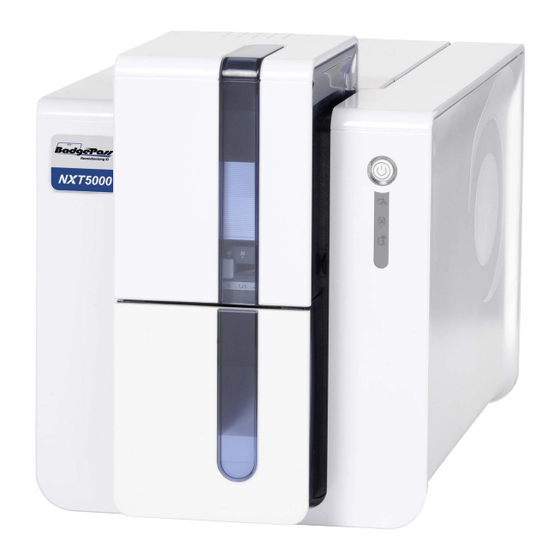
Service Manual Description Picture 1: BadgePass NXT5000 Printer Page 10... -
Page 11: Explode View
Service Manual Explode View Drawing 1 Page 11... - Page 12 Service Manual Spare Parts List FEEDER: EXIT HOPPER BLUE S10126 BELTS: FEEDER KIT FEEDER: UPPER BLUE S10092 S10124 BELTS: TIGHTING KIT MOTOR: COMMON S10094 S10097 Drawing 3 Page 12...
- Page 13 Service Manual Spare Parts List RIBBON: BRAKING KIT S10093 BELTS: TRANSPORT KIT S10091 SENSOR: FLEX KIT S10088 MOTOR: STEPPER S10096 MOTOR: COMMON S10097 Drawing 4 Page 13...
- Page 14 Service Manual Spare Parts List RIBBON: DETECTION KIT (WITH CABLE) S10087 MOTOR: STEPPER, FEEDER S10098 BELTS: TRANSPORT KIT S10091 MOTOR: COMMON S10097 Drawing 5 Page 14...
- Page 15 Service Manual Spare Parts List ROLLER: HEAD KIT S10099 SENSOR: FLIP OVER S10121 ROLLER: CLEANING S10122 FLIP-OVER: MODULE S10128 Drawing 6 Page 15...
- Page 16 Service Manual Spare Parts List HEAD BRACKET S10135 PRINT HEAD: KPE S10084 SENSOR: RIBBON CABLE: PRINT HEAD FAN: KIT S10089 S10085 S10100 Drawing 7 Page 16...
- Page 17 Service Manual Spare Parts List MAIN BOARD: USB ETH USB-HUB S10114 Drawing 8 PACKAGING: BOX AND FOAM S10127 Drawing 9 Page 17...
-
Page 18: Spare Parts List
Service Manual Spare Parts List Name Description Step Product Code CI010222 Reject Box CI010214 Enclosure Side S10086 LCD and Control Panel with Cable Upper Blue Feeder S10124 S10126 Exit Hopper Blue Feeder S10092 Feeder Belts Kit S10094 Tighting Belts Kit 7-19-20 S10097 Common Motor... -
Page 19: Available Tools
Service Manual Available Tools Flat screwdriver AR 2.5X75 Precision clamp Torx Flat Bolt Picture 2: Tools Page 19... -
Page 20: Step 1 - Reject Box - Ci010222
Service Manual Step 1 - Reject Box - C1010222 1. Lift the box to remove it. Picture 3: Reject Box Page 20... -
Page 21: Step 2 - Enclosure Side Ci010214
Step 2 - Enclosure Side Service Manual CI010214 1. Press and open the cover. Picture 4: Top Cover 2. Press and open the side. Picture 5: Side Bolt 3. Push and unplug the enclosure side. (side by side) Picture 6: Enclosure Side Page 21... -
Page 22: Step 3 - Lcd Control Panel (With Cable) - S10086
Step 3 - LCD Control Panel Service Manual (with cable) - S10086 1. Disconnect the LCD cable. 2. Remove the two screws. Picture 7: Control Panel Page 22... - Page 23 Step 4 - Upper and Hopper Feeder Service Manual S10123 1. First, be sure to have completely performed Step 2. 2. Remove the two screws. Picture 8: Feeder inside Right Side 3. Remove the three screws and the feeder cable. Picture 9: Feeder inside Left Side 4.
-
Page 24: Step 4 - Upper And Hopper Feeder - S10123 To S10126
Step 4 - Upper and Hopper Feeder Service Manual S10126 5. Push the belt idler and remove the belt in the same time. 6. Unclip and push the upper feeder a little in the same time. Picture 11: Feeder Right Side 4. -
Page 25: Step 5 - Feeder Belts Kit S10092
Step 5 - Feeder Belts Kit Service Manual S10092 1. Disconnect the LCD cable. 2. Remove the two screws. Picture 13: Feeder Belt Page 25... -
Page 26: Step 6 - Tighting Belts Kit S10094
Step 6 - Tighting Belts Kit Service Manual S10094 1. First, be sure to have completely performed from Step 4-1 to Step 4 – 5. 2. Remove the spring. Picture 14: Feeder Tighting Belt 3. Push and remove the belt idler. Picture 15: Feeder Tighting Belt-1 Page 26... -
Page 27: Step 7 - Common Motor S10097 (Feeder)
Step 7 - Common Motor Service Manual S10097 (Feeder) 1. First, be sure to have completely performed Step 5. 2. Remove the E-Ring and the pulley. Picture 16: Feeder E-ring & pulley 3. Push and remove the belt idler. Picture 17: Feeder Motor Cable Page 27... - Page 28 Step 7 - Common Motor Service Manual S10097 (Feeder - Continued) 1. First, be sure to have completely performed Step 5. 2. Remove the E-Ring and the pulley. Picture 18: Feeder Motor-1 5. Remove the motor. Picture 19: Feeder Motor-2 Page 28...
-
Page 29: Step 8 - Enclosure Base Ci011190
Step 8 - Enclosure Base Service Manual CI011190 1. First, be sure to have completely performed from Step 4-1 to Step 4 – 4. 2. Be sure to have completely performed Step 3-1. 3. Loosen the two screws on each side. Picture 20: Enclosure Base side 4. -
Page 30: Step 9 - Flip Over Sensor S10121
Step 9 - Flip Over Sensor Service Manual S10121 1. First, be sure to have performed Step 2 without Step 2 -3. 2. Remove the flip sensor and disconnect its cable. Picture 23: Flip Sensor Page 30... -
Page 31: Step 10 - Ribbon Braking Kit S10093
Step 10 - Ribbon Braking Kit Service Manual S10093 1. First, be sure to have performed Step 2 without Step 2 -3. 2. Remove the option roller gear. 3. Push and turn left the lock and remove it. Picture 24: Ribbon lock 4. - Page 32 Step 10 - Ribbon Braking Kit Service Manual S10093 (Continued) 6. Remove the gear if necessary. Picture 26: Ribbon lock gear *Be careful, when you put back the black gears put the gears like on the picture 48 Step21. Page 32...
-
Page 33: Step 11 - Transport Belts Kit S10091
Step 11 - Transport Belts Kit Service Manual S10091 1. Transport belt (a) First, be sure to have completely performed Step 8. (b) Remove the transport belt. Picture 27: Transport Belt 2. Black Ribbon belt (a) First, be sure to have performed Step 2 without Step 2 -3. - Page 34 Step 11 - Transport Belts Kit Service Manual S10091 (Continued) 3. Ribbon belt 4. Stepper belt (a) First, be sure to have performed Step 2 without Step 2 -3. (b) Remove the ribbon belt. (c) Remove the head roller gear (a) and the stepper belt. Picture 29: Tansport Belts 5.
-
Page 35: Step 12 - Ribbon Detection Kit S10087
Step 12 - Ribbon Detection Kit Service Manual S10087 1. First, be sure to have completely performed Step 2. 2. Disconnect the cable on the main board. 3. Remove the rivet. Picture 31: Ribbon Detection 4. To Put back the rivet, push it from the inside printer. Picture 32: Ribbon Detection Rivet Page 35... -
Page 36: Step 13 - Stepper/Feeder Motor S10098
Step 13 - Stepper/Feeder Motor Service Manual S10098 1. First, be sure to have completely performed Step 2. 2. Disconnect the motor cable you want. 3. Remove the motor rivet you want to replace. Picture 33: Motor Flip Page 36... -
Page 37: Step 14 - Flip Over Module S10128
Step 14 - Flip Over Module Service Manual S10128 1. First, be sure to have completely performed Step 8. 2. Press and turn at the same time the flip sensor support. Picture 34: Flip Sensor 3. Remove the flip motor. (For more details, refer to Step Picture 35: Flip Motor Page 37... - Page 38 Step 14 - Flip Over Module Service Manual S10128 (Continued) 4. Press and turn at the same time the flip support. Picture 36: Flip Support 5. Remove the flip over. Picture 37: Flip Over Page 38...
-
Page 39: Step 15 - Cleaning Roller S10122
Step 15 - Cleaning Roller Service Manual S10122 1. First, be sure to have completely performed Step 2-1. 2. Press on the plastic latch and remove the cleaning roller. Picture 38: Cleaning Roller Page 39... -
Page 40: Step 16 - I/O Shield Ci010322
Step 16 - I/O Shield Service Manual CI010322 1. First, be sure to have completely performed Step 8. 2. Remove the I/O Shield. Picture 39: I/O Shield Page 40... -
Page 41: Step 17 - Enclosure Bottom Plate Se010079
Step 17 - Enclosure Bottom Plate Service Manual SE010079 1. First, be sure to have completely performed Step 8. 2. Press on the bottom plate clip (a) and push on the left (b) in the same time to remove the module. Picture 40: Bottom Plate Page 41... -
Page 42: Step 18 - Main Board Usb Eth S10114
Step 18 - Main Board USB ETH Service Manual S10114 1. First, be sure to have completely performed Step 17. 2. Remove all the connectors and the flex connector. Picture 41: MainBoard Connections 3. Turn back the primacy chassis and remove the three screws. Picture 42: Fixing MainBoard Page 42... -
Page 43: Step 19 - Common Motor S10097 (Up And Down)
Step 19 - Common Motor Service Manual S10097 (Up and Down) 1. First, be sure to have completely performed Step 18. 2. Unclip the gear motor and cable. Picture 43: Gear Motor 3. Press on the motor clip with a flat screwdriver and turn the motor at the same time. Picture 44: Motor Clip Page 43... -
Page 44: Step 20 - Common Motor - S10097 (Ribbon)
Step 20 - Common Motor Service Manual S10091 (Ribbon) 1. First, be sure to have completely performed Step 18. 2. Remove the ribbon belt, the ribbon pulley and the motor cable. Picture 45: Common Motor Left Side 3. Press on the motor clip with a flat screwdriver and turn the motor at the same time. Picture 46: Common Motor clip Page 44... -
Page 45: Step 21 - Stepper Motor S10096
Step 21 - Stepper Motor Service Manual S10096 1. First, be sure to have completely performed Step 18. 2. Remove the motor cable and the gear. Picture 47: Stepper Motor 3. Remove the MXL belt and the gear. Picture 48: Transport Belt Page 45... - Page 46 Step 21 - Stepper Motor Service Manual S10096 (Continued) 4. Remove the two screws of the belt idler. Picture 49: Belt Idler screws 5. Remove the two screws of the Stepper motor. Picture 50: Stepper Motor 6. When you will re-assembly components; Be carreful, when you put back the black gears, to align the markers together.
-
Page 47: Step 22 - Head Roller Kit - S10099
Step 22 - Head Roller Kit Service Manual S10099 (Continued) 1. First, be sure to have completely performed Step 14. 2. Remove the parts indicated on the bellow. ( Picture 52) Picture 34: Flip Sensor 3. Remove the Stepper belt. Picture 53: Stepper Belt Page 47... - Page 48 Step 22 - Head Roller Kit Service Manual S10099 (Continued) 4. Press and turn at the same time the flip support. Picture 54: Transport Belt 5. Remove the two screws on each side of the module. Picture 55: Disassembly Chassis screws Page 48...
- Page 49 Step 22 - Head Roller Kit Service Manual S10099 (Continued) 6. Open the head bracket, lift and pull forward and remove the upper chassis. Picture 56: Separation of Chassis 7. Remove the synchro ribbon support and the spring of the pressure roller. Picture 57: Synchro Ribbon Support Page 49...
- Page 50 Step 22 - Head Roller Kit Service Manual S10099 (Continued) 8. Remove the option roller and the two springs. Picture 58: Option roller & springs 9. Tilt forward the head roller kit and lift up it Picture 59: Heat Roller -1 Picture 60: Heat Roller - 2 When you will re-assembly all components;...
-
Page 51: Step 23 - Flex Sensor Kit S10088
Step 23 - Flex Sensor Kit Service Manual S10088 1. First, be sure to have completely performed Step 22. 2. Remove the flag and disconnect the flex. Picture 61: Flex connector 3. Press on the two sides of the up and down sensor and remove it. 4. - Page 52 Step 23 - Flex Sensor Kit Service Manual S10088 5. Remove the card sensor. Picture 63: Flex Card Sensor Be carreful, when you’ll put back the black gears put the gears like the picture 51 Step 21-6. Page 52...
-
Page 53: Step 24 - Print Head (Kpe) S10084
Step 24 - Print Head (KPE) Service Manual S10084 1. First, be sure to have completely performed Step 2-1. 2. Press on the plastic part behind the head (pressure plate) and pull on the head with the other hand to free the lugs from the holding fork, and then remove the lugs from their slots. -
Page 54: Step 25 - Ribbon Sensor S10089
Step 25 - Ribbon Sensor Service Manual S10089 1. First, be sure to have completely performed Step 2-1. 2. Disconnect the sensor cable. Picture 67: Ribbon Sensor - 1 3. Unclip the upper sensor support (a), unclip the lower sensor support and remove it (b). Picture 68: Ribbon Sensor - 2 3. -
Page 55: Step 26 - Enclosure Cover Ci010205
Step 26 - Enclosure Cover Service Manual CI010205 1. First, be sure to have completely performed Step 2-1. 2. With a screwdriver push on the cover clip and move it in the same time on each side. Picture 70: Enclosure Cover - 1 3. -
Page 56: Step 27 - Enclosure Buttom Ci010206
Step 27 - Enclosure Buttom Service Manual CI010206 1. First, be sure to have completely performed Step 2-1. 2. Push on the button clip. Picture 72: Enclosure Button Page 56... -
Page 57: Step 28 - Fan Kit S10100
Step 28 - Fan Kit Service Manual S10100 1. First, be sure to have completely performed Step 8 Step 26. 2. Remove the filter fan. Picture 73: Fan - 1 3. Remove the two rivets. 4. Disconnect the fan cable. Picture 74: Fan Connector Page 57... - Page 58 Step 28 - Fan Kit Service Manual S10100 (Continued) 5. Pass the fan cable thru the chassis cable path. Picture 75: Fan Cable Path 5. Remove the two screws on each side of the module. Picture 76: Fan - 2 Page 58...
-
Page 59: Step 29 - Print Head Cable S10085
Step 29 - Print Head Cable Service Manual S10085 1. First, be sure to have completely performed Step 8 Step 26. 2. Disconnect the print head cable. Picture 77: Print Head Cable – Print Head Connector 3. Disconnect the print head cable. Picture 78: Print Head Cable –... -
Page 60: Step 30 - Head Bracket S10138
Step 30 - Head Bracket Service Manual S10138 1. First, be sure to have completely performed Step Step Step 26 Step 2. Disconnect the three cables. Picture 80: Head Bracket Connectors 3. Pass the cables thru the chassis. 4. Remove the E-ring. Picture 81: Head Bracket Cables Path 5.
Need help?
Do you have a question about the BadgePass NXT5000 and is the answer not in the manual?
Questions and answers