Table of Contents
Advertisement
Quick Links
Advertisement
Table of Contents

Related Manuals for Ultrak KC440xMP


Summary of Contents for Ultrak KC440xMP
-
Page 1: Instruction Manual
1/3" CCD BLACK & WHITE CAMERA INSTRUCTION MANUAL Worldwide Support Center 1301 Waters Ridge Drive • Lewisville, TX 75057 (800) 796-2288 (972) 353-6400 FAX (972) 353-6670 • • Please read this manual thoroughly before use, and keep it handy for future reference. - Page 2 ULTRAK MAKES NO EXPRESS OR IMPLIED WARRANTIES OF ANY NATURE AS TO THE PRODUCTS INCLUDED HEREIN AND SPECIFICALLY DISCLAIMS ALL WARRANTIES OF MERCHANTABLILTY AND FITNESS FOR A PARTICULAR PURPOSE.
-
Page 3: Explanation Of Graphical Symbols
WARNING: TO REDUCE THE RISKOFFIREOR ELECTRIC SHOCK, DO NOT EXPOSE THIS PRODUCT TO RAIN OR MOISTURE.DO NOT INSERT ANY METALLIC OBJECT THROUGH VENTILATION GRILLS. CAUTION: Explanation of Graphical Symbols The lightning flash with arrowhead symbol, within an equilateral triangle, is intended to alert the user to the presence of uninsulated "dangerous voltage"... - Page 4 IMPORTANT SAFEGUARDS IMPORTANT SAFEGUARDS READ INSTRUCTIONS -- All the safety and operating LIGHTNING -- For added protection for video equipment instructions should be readbeforetheapplianceis operated. during a lightning storm, or when it is left unattended and unused for long periods of time, unplug it from the wall outlet RETAIN INSTRUCTIONS -- The safety and operating and disconnect the antenna or cable system.
-
Page 5: Table Of Contents
TABLE OF CONTENTS PURPOSE INSTALLATION PRECAUTIONS SYSTEM INSTALLATION MAJOR OPERATING CONTROLS AND THEIR FUNCTION MAJOR OPERATING CONTROLS AND THEIR FUNCTION LENS ADJUSTMENT TROUBLESHOOTING MAINTENANCE SPECIFICATION - 5 -... - Page 6 THIS PAGE INTENTIONALLY LEFT BLANK - 6 -...
-
Page 7: Purpose
PURPOSE The CCD Black & White Camera provides a low cost solution to closed circuit television and security surveillance applications. The camera features : • 1/3" interline transfer CCD image sensor • Supports standard CS or C-mount lens • Equipped with electronic iris •... -
Page 8: System Installation
SYSTEM INSTALLATION Installation of the camera must be performed by qualified service personnel in accordance with all local and national electrical and mechanical codes. Perform the following steps to install the camera. Remove all components from the package and identify the items that will be used during installation: •... - Page 9 Route the video cable from the monitor to the camera. Plug the cable into the BNC output connector labeled " VIDEO OUT" on the rear of the camera. Plug the other end of the cable into the video input port on the rear of the monitor. <...
-
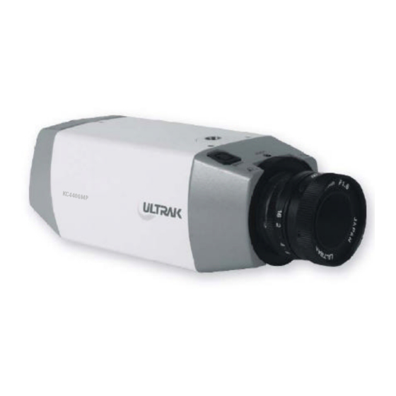
Page 10: Top View
< TOP VIEW > 6. Video Out BNC Connector 3. Auto Iris Connector 4. Stand Mount Bracket(up) 1. C/CS Back Focus Adjust Ring 2. Back Focus Lock Screw 5. Function Switch 2. Back Focus 3. Auto Iris Lock Screw Connector 6. -
Page 11: Major Operating Controls And Their Function
MAJOR OPERATING CONTROLS AND THEIR FUNCTION 1. Focus Adjust Ring This ring is used to adjust the back focal length or picture focus by rotating this ring to clockwise for CS-mount lens or counterclockwise for C-mount. 2. Back Focus Lock Screw This screw is used to lock the focus adjust ring. - Page 12 B. E/I (Electronic IRIS) / (ON / OFF) Automatically varies the camera's shutter to mimic auto iris control, allowing fixed or manual iris lenses to be used in a wider range of area. When this function is used, turn off the F/F switch. C.
-
Page 13: Lens Adjustment
LENS ADJUSTMENT 1. MANUAL IRIS LENS When using the manual iris lens, turn the iris ring on the lens to the OPEN position and adjust the manual iris for the appropriate range. Adjust during the brightest conditions, oening the lens without saturating the picture. - Page 14 Plug the connector into the auto iris jack on the top of the camera. The connector is polarized and can only be inserted into the jack one way. The E/I switch should be in the "off "position. The A/I switch should be in the "vid" position. Apply power to the camera.
- Page 15 3. DC-TYPE AUTO IRIS LENS The camera supports an auto iris lens. To install and adjust a DC-type auto iris lens, do the following: Thread the auto iris lens onto the lens mount on the front of the camera. (see figure 4.) Solder the lens control wires to the connector supplied with the camera.
- Page 16 4. BACK FOCUS ADJUSTMENT For best results, perform back focus adjustments at night or while using a #6 or #8 welders glass in front of the lens. The focus of the camera will change slightly if the camera iris was adjusted on a light scene, then changes to a dark scence.
- Page 17 5. ZOOM LENS BACK FOCUS ADJUSTMENT The objective of back focusing a zoom lens is similar to that of a fixed focal length camera, except that back focus is also adjusted to maintain the focus when "zooming" the lens in and out on a scene. Choose an object at the farthest range that you wish to look at with a zoom lens.
-
Page 18: Troubleshooting
TROUBLESHOOTING If problems occur, verify the installation of the camera with the instructions in this manual and with other operating equipment. Isolate the problem to the specific piece of equipment in the system and refer to the equipment manual for further information. Problem Possible Solution 1. -
Page 19: Specification
SPECIFICATIONS Image sensor Picture Element (H x V) Image sensor area (H x V) Resolution Min. scene illumination S/N Ratio Shutter speed Line phase range Sync system Signal format Scanning frequency(H x V) Video output Power requirements Power consumption Connector - Video out - Auto iris Lens mount - 19 -... - Page 20 Dimension(WxHxD) Weight Ambient temperature Ambient humidity Funtion - E/I - A/I - IRIS - PHASE Printed in KOREA Rev - Part 50300954...
Need help?
Do you have a question about the KC440xMP and is the answer not in the manual?
Questions and answers