Table of Contents
Advertisement
Quick Links
1/3" DSP
COLOR
SECURITY
CAMERA
(NTSC)
USER MANUAL
Corporate Headquarters & Eastern Regional Office:
1301 Waters Ridge Lewisville, TX 75057
(800) 796-2288 (972) 353-6400 FAX (972) 353-6670
Western Regional Office:
6252 West 91st Avenue Westminster, CO 80030
(800) 846-8884 (303) 428-9480 FAX (303) 429-6609
KC5300
Advertisement
Table of Contents

Related Manuals for Ultrak KC5300


Summary of Contents for Ultrak KC5300
-
Page 1: User Manual
KC5300 1/3" DSP COLOR SECURITY CAMERA (NTSC) USER MANUAL Corporate Headquarters & Eastern Regional Office: 1301 Waters Ridge Lewisville, TX 75057 (800) 796-2288 (972) 353-6400 FAX (972) 353-6670 Western Regional Office: 6252 West 91st Avenue Westminster, CO 80030 (800) 846-8884 (303) 428-9480 FAX (303) 429-6609... - Page 2 (303) 428-9480 ALL RIGHTS RESERVED. NO PART OF THIS PUBLICATION MAY BE REPRODUCED BY ANY MEANS WITHOUT WRITTEN PERMISSION FROM ULTRAK. THE INFORMATION IN THIS PUBLICATION IS BELIEVED TO BE ACCURATE IN ALL RESPECTS. HOWEVER, ULTRAK CANNOT ASSUME RESPONSIBILITY FOR ANY CONSEQUENCES RESULTING FROM THE USE THEREOF.
- Page 3 AND COMPLYING WITH ALL FEDERAL, STATE, AND LOCAL LAWS AND STATUTES CONCERNING THE MONITORING AND RECORDING OF VIDEO AND AUDIO SIGNALS. ULTRAK SHALL NOT BE HELD RESPONSIBLE FOR THE USE OF THIS PRODUCT IN VIOLATION OF CURRENT LAWS AND STATUTES.
-
Page 4: Important Safeguards
IMPORTANT SAFEGUARDS READ INSTRUCTIONS - Read all safety and operating instructions before operating this product. RETAIN INSTRUCTIONS - Retain the safety and operating instructions for future reference. CLEANING - Unplug all equipment before cleaning. Do not use liquid cleaners or aerosol cleaners. -
Page 6: Table Of Contents
TABLE OF CONTENTS PURPOSE..................1 SYSTEM INSTALLATION ............1 WHITE BALANCE ADJUSTMENT (WBA)........6 CAMERA ADJUSTMENTS ............6 MANUAL IRIS LENS ADJUSTMENT........... 7 VIDEO-TYPE AUTO-IRIS LENS INSTALLATION & ADJUSTMENT ................7 DC-IRIS LENS INSTALLATION AND ADJUSTMENT ....9 DC IRIS BACK FOCUS ADJUSTMENT ........11 ZOOM LENS BACK FOCUS ADJUSTMENT ...... -
Page 7: Purpose
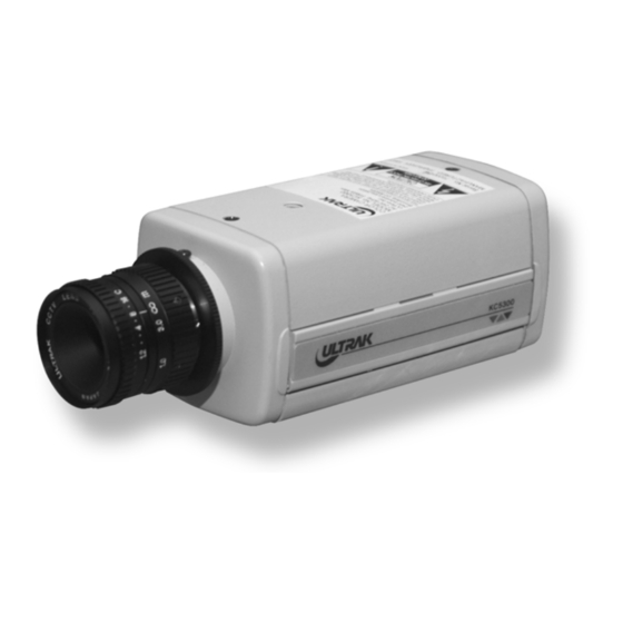
Excellent picture quality • Flexible configuration • Two-year warranty This manual describes how to set up and operate the KC5300 camera. SYSTEM INSTALLATION Installation of the KC5300 camera must be performed by qualified service personnel in accordance with all local and national electrical and mechanical codes. - Page 8 Coaxial cable • Camera stand or mounting bracket • 24V ac power supply • Mounting hardware • Security monitor Refer to the following figures for identification of the KC5300 camera. FIGURE 1. TOP OF CAMERA FIGURE 2. BOTTOM OF CAMERA...
- Page 9 FIGURE 3. BACK OF CAMERA FIGURE 4. FRONT OF CAMERA...
- Page 10 D. The KC5300 camera has a threaded mounting hole on the bottom and top of the camera housing to allow for bottom or top mounting. The ¼"-20 UNC threaded mounting hole attaches to the bolt on the camera stand or mounting bracket.
- Page 11 F. If an auto-iris lens is used, connect the cable to the terminal block for a video-type auto-iris lens. If using a DC iris lens, use the mini-DIN connector supplied with the camera. G. Route the coaxial cable from the monitor to the camera. H.
-
Page 12: White Balance Adjustment (Wba)
SECTION 2 KC5300 CAMERA ADJUSTMENTS WHITE BALANCE ADJUSTMENT (WBA) This adjustment is used to place the white balance function of the camera into the AUTO (automatic) mode. If the switch is placed in the AUTO position, the camera will automatically try to maintain white objects as white even if the light color changes. -
Page 13: Manual Iris Lens Adjustment
VIDEO-TYPE AUTO-IRIS LENS INSTALLATION & ADJUSTMENT The KC5300 camera supports video-type auto iris lenses to adjust for changing light levels. Perform the following steps to install and adjust a video-type auto-iris lens. - Page 14 Name Wire Color Voltage + Video White Ground Black C. Apply power to the camera. D. Adjust the focus ring on the lens for an optimum picture. If a picture is not visible, set the lens for proper exposure by adjusting the ALC (automatic level control) and Level on the lens.
-
Page 15: Dc-Iris Lens Installation And Adjustment
3. Reset the level control as noted in step E. DC-IRIS LENS INSTALLATION AND ADJUSTMENT The KC5300 camera supports a dc-iris lens. To install and adjust a dc-type auto-iris lens, do the following: A. Thread the dc-iris lens onto the lens mount on the front of the camera. - Page 16 FIGURE 7. LENS CONTROL CONNECTIONS C. Plug the connector into the DC-IRIS jack on the back of the camera. The connector is polarized and can only be inserted into the jack one way. FIGURE 8. CAMERA SIDE AND BACK VIEW...
-
Page 17: Dc Iris Back Focus Adjustment
D. Apply power to the KC5300 camera. E. Adjust the dc-iris lens for an optimum picture. Use the IRIS LEVEL control on the back of the camera for optimum picture quality. DC IRIS BACK FOCUS ADJUSTMENT For best results, perform back focus adjustments at night or while using a #6 or #8 welder’s glass in front of the lens. -
Page 18: Phase Adjustment
A. Choose an object at the farthest range that you wish to look at with a zoom lens. B. Make sure the iris of the lens is wide open. (Do this by adjusting the camera at night or use a welder’s glass in front of the lens.) C. - Page 19 B. Adjust the phase control on the side of the camera until there is no vertical flip or roll on the monitor when using the auto- switcher. FIGURE 9. PHASE CONTROL...
-
Page 20: Dave Address Configuration
SECTION 3 CAMERA CONFIGURATIONS FOR DAVE™ SYSTEMS DAVE ADDRESS CONFIGURATION Use the following chart for camera address switch settings in systems using Ultrak’s DAVE technology. FIGURE 10. CAMERA ADDRESS SWITCH SETTINGS ADDRESS SW 1 SW 2 SW 3 SW 4... -
Page 21: Dave Alarm Configuration
DAVE ALARM CONFIGURATION The KC5300 camera’s alarm port can be used for normally open or normally closed alarms. Programming of the alarm polarity is accomplished through the DAVE configuration setup. In DAVE-based systems, alarms can be connected to the individual camera or to the DAVE Loop Encoder. - Page 22 FIGURE 12. DAVE DUAL OUTPUT CONFIGURATION...
-
Page 23: Troubleshooting
SECTION 4 TROUBLESHOOTING AND MAINTENANCE TROUBLESHOOTING If problems occur, verify the installation of the camera with the instructions in this manual and with other operating equipment. Isolate the problem to the specific piece of equipment in the system and refer to the equipment manual for further information. Problem Possible Solution No Video... -
Page 24: Specifications
SPECIFICATIONS ELECTRICAL: Image sensor 1/3-inch color CCD Active pixels 512H x 492V Image sensor area 4.9H x 3.7V mm Resolution >330 Horizontal TV lines Min. scene illumination 3.0 Lux (F 1.2, 50% IRE) >46 dB Gamma correction 0.45 Internal, automatic Electronic Iris Selectable, on/off Back-light...
Need help?
Do you have a question about the KC5300 and is the answer not in the manual?
Questions and answers