Table of Contents
Advertisement
Quick Links
CVR811
Model:
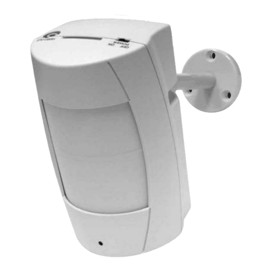
Portable Colour Covert
PIR Camera & DVR
Before you begin
•
Please unpack the box carefully and identify that all the parts are present.
The camera is suitable for indoor use only. Please bear in mind the following points when
choosing a mounting position.
•
The camera must be positioned so that it will not point directly into the sun (sunrise and
sunset) or any bright light, as this may cause damage to the camera.
•
Avoid viewing areas where half the area is in bright sunlight and the other half is dark,
such as in the shadow of a building. All types of cameras have difficulty in 'seeing' with
such a large lux level variation.
•
Do not cut the camera cables, this will void the warranty.
•
Make sure you use only the recommended power supply. Damage caused to the camera by
incorrect voltage or wiring is not covered by the warranty.
Model:
CVR811
Portable Colour Covert PIR
Camera & DVR
CCTV
Advertisement
Table of Contents

Subscribe to Our Youtube Channel
Related Manuals for XVision CVR811


Summary of Contents for XVision CVR811
-
Page 1: Before You Begin
CCTV CVR811 Model: Portable Colour Covert PIR Camera & DVR Before you begin • Please unpack the box carefully and identify that all the parts are present. The camera is suitable for indoor use only. Please bear in mind the following points when choosing a mounting position. -
Page 2: Safety Precautions
Thank you for purchasing this Xvision camera. Before operating this product, please read this instruction manual carefully. 1. Safety Precautions The power cord is the main power connection. Avoid constant plugging and unplugging of the power cord as this may result in a malfunction of the product. - Page 3 Supports 12V DC or 4xAA batteries (use if power outlet is not located near the camera site). External SD card slot. 4. Contents Video Lead Camera Bracket CVR811- Portable Colour Power Supply Screws and Wall Plugs Covert PIR Camera & DVR...
-
Page 4: Installation
5. Installation Please refer to the instructions below for camera mounting, bracket installation and monitor connection: 5.1 Bracket Fixing Guide 5.2 Camera Mounting Guide 5.3 Video Output and Power Supply Connection Guide Connect one end of the video lead to Video Out on the top of the camera unit, and the other end to the Video Input of your monitor... -
Page 5: Back Panel
6. Functions 6.1 Back Panel 2 SD Card Socket 5 Video Out 3 Power Switch (On/Off) 6 LED Mode Indicator 1 Function Dip Switch 7 Function Buttons 8 LED Power Indicator 4 Power Input 6.1.1 Function Switch NTSC <-> PAL The two most common video standards used are NTSC and PAL. -
Page 6: Function Description Table
6.1.4 Power Input Connect 12V DC Power Supply to enable the unit to be powered by the mains. 6.1.5 Video Output Jack To enable monitoring functions, connect one terminal to the video out jack and the other terminal to the monitor (TV). 6.1.6 LED Operation Mode Indicators LED light easily allows the user to distinguish the current system status. -
Page 7: Monitoring Mode
Power On 1. The power switch is situated on the right side of the device. NOTE: Each time after power-on, the system auto-detects its peripherals. When the REC LED flashes this indicates that the system memory is initiating auto test sequence (complete boot time is several seconds). When an image file error has been detected, the system will initiate auto repair sequence. -
Page 8: Record Mode
6.3 Record Mode 6.3.1. Start Record: 3 Types of recording mode. (1) Manual Record: Suitable for recording at anytime. Press <<Rec I / G >> button, to enter manual recording status (start recording). For more information, please refer to [7.4 Record Setup]. (2) Motion Detection Record: Suitable for recording, when there are severe image changes. -
Page 9: Playback Mode
6.3.6. Video or audio may be recorded to the system memory. When the video has been stored, the Rec LED flashes indicating that the system is currently loading the file to the system memory. 6.3.7. No matter which record mode is used, please enter the main menu (Refer to 7.1 Main Menu) before switching off the power. - Page 10 6.4.2 Search and Playback: Enter MENU and select [SEARCH AND PLAY] item. 1 File directory shows dates and the amount of contents under the directory. The user may press << >> or << >> button to move the cursor up or down. 2 Current location page.
-
Page 11: Date/Time Setup
7. System Setup 7.1 Main Menu 1 Main Menu: Item subject. 2 Menu Layer Indication: The device consists of three menu layers. : First Menu Layer (Main Menu) : Second Menu Layer : Third Menu Layer 3 Menu Content: Basic Menu Operations. Press <<... -
Page 12: Motion Detection Setup
7.3 Motion Detection Setup 7.3.1. Motion detection sensitivity rate setup: Changing the threshold value setup may affect the recording sensitivity of the Motion Detection. 1 Sensitivity Bar: Color black indicates image variable value and color red indicates the MD threshold. 2 MD Energy: Current image variation value. - Page 13 7.4.2. SCHEDULE RECORD (CONTINUOUS/MOTION DETECTION): Schedule Record: Records only within a preset time range. RECORD: Enable or disable schedule recording (ON/ OFF). SCHEDULE: Hh:Mm –Hh:Mm = 24 hour recording and 00:00–00:01 = Recording of one minute image from 00: 00 to 00:01. Motion Detection Recording - DURATION TIME Setup: DURATION: Duration of recording time when motion detection has been triggered...
-
Page 14: Factory Default
7.6 Factory Default Press <<->> or <<+>> button to return all settings to the factory default value. Press <<Stop I / Exit>> button, exit the current screen display and return to the Main Menu. NOTE: Return to factory default will erase all configuration values and return to the Factory Default values (except Date and Time setup). -
Page 15: Specifications
8. Specifications Model: CVR811 Picture Type: Colour Image Sensor: 1/6” CMOS Sensor Resolution: < 330TVL Lens Viewing Angle: 72° Infra Red Nightvision: Minimum Illumination: 0.9 Lux > Lens Board Lens f3.62mm / F2.8 Effective Picture Element VGA (H/V: 640x480) S/ N Ratio... - Page 16 CCTV TECHNICAL SUPPORT: For Technical Support for any Xvision product please contact your local distributor. LIMITED WARRANTY: This product is supplied with a 2 Year warranty. The Warranty excludes products that have been misused, (including accidental damage) and damage caused by normal wear and tear. In the unlikely event that you encounter a problem with this product, it should be returned to the place of purchase.
Need help?
Do you have a question about the CVR811 and is the answer not in the manual?
Questions and answers