Table of Contents
Advertisement
Ride-on Brushcutter
CM141 CM142
Operator's Manual
Read this manual completely before operating or maintaining this machine.
Failure to follow safety precautions could result in serious injury or death.
Keep this manual for future reference by you and by all those who operate
and maintain this machine.
Original Instructions
(in English)
CHIKUSUI CANYCOM, INC.
90-1 Fukumasu, Yoshii-machi,
Ukiha-shi, Fukuoka, Japan 839-1396
Tel.+81-(0)943-75-2195 Fax.+81-(0)943-75-4396
5343 5204 001 01
Advertisement
Table of Contents

Related Manuals for CanyCom CM141

Summary of Contents for CanyCom CM141
- Page 1 Ride-on Brushcutter CM141 CM142 Operator's Manual Read this manual completely before operating or maintaining this machine. Failure to follow safety precautions could result in serious injury or death. Keep this manual for future reference by you and by all those who operate and maintain this machine.
- Page 2 CHIKUSUI CANYCOM, INC. http://www.canycom.co.jp/ Sales Headquarters TEL +81-(0)943-75-2195 FAX +81-(0)943-75-4396 ■ Foreign Trade Center TEL +81-(0)3-3552-6277 FAX +81-(0)3-3552-6288 ■ Authorized Dealer All rights reserved. Unauthorized use or reproduction of this material is prohibited.
-
Page 3: Safety Labels
Notice to Users and Maintenance Personnel Thank you for purchasing this machine. This manual provides information needed for safe and effective use of this machine to those who operate or maintain machine. Make sure to read and understand the manual thoroughly before operating this product. - Page 4 Notice to Owner • Be sure that everyone who uses this machine, including those who rent or lease this machine, receives a copy of this Operator's Manual and understands the importance of reading and following the information in this manual. Warning Terms Used in this Manual In this manual, the following four warning terms are used to signal the four levels of hazard (or seriousness of possible accidents).
- Page 5 Warranty and After-Sales Service Warranty CHIKUSUI CANYCOM, INC. guarantees this product, based on the terms of warranty. A copy of this warranty is reproduced in the back of this manual. After-Sales Service Consult your local CANYCOM dealer or our company’s sales department regarding service orders or any questions or problems that may arise when using this machine.
-
Page 6: Table Of Contents
Contents 1. Safety Safety Labels ........1 Safety Mechanisms . - Page 7 Driving ........17 Starting .
- Page 8 Drive Train........44 Tires ............44 Transmission Oil .
- Page 9 7. Transporting Hauling ........67 Loading and Unloading .
-
Page 10: Safety
• Replace these labels immediately if they have been removed, have fallen off or become illegible. Use the part number, on the label or shown in this manual, to order a replacement label from your CANYCOM representative. (Back of the seat) -
Page 11: Safety Mechanisms
Safety 5305 5317 002 5321 5113 000 5321 5113 000 CAUTION ATTENTION VORSICHT CAUTELA PRECAUCIÓN To avoid fire 1. Supply fuel only after engine and muffler have cooled. Fill tank to upper fuel limit. 2. When operating machine on slopes, always refuel to level below upper fuel limit. 3. -
Page 12: Safety Precautions
Safety Safety Precautions This section contains safety precautions to follow when operating and maintaining the machine. Read and understand the precautions in this section as well as throughout this manual and follow them when operating or maintaining the machine. Failure to follow safety precautions could result in property damage, serious injury or death to the operator or bystanders. -
Page 13: Preparation
Safety Preparation • Fuel is highly flammable. See Checking and Filling Fuel, page 15, for important safety information on handling fuel. • Always wear protective footwear, long trousers, hardhat, safety glasses and ear protection when operating or servicing the machine. Proper clothing will minimize the chance of injury. - Page 14 Safety General Driving • Do not operate the engine in a confined space where dangerous carbon monoxide fumes can accumulate. • Do not touch the engine, muffler or exhaust pipe while the engine is running or soon after it has stopped. These areas will be very hot and can cause burns. •...
- Page 15 Safety • Do not make sudden maneuvers. A sudden start, stop, or turn can make the machine lose control and could cause a tip over. Be especially cautious when traveling on soft or wet ground. • Drive at a safe speed, taking into account the surface gradient, surface conditions and load.
- Page 16 Safety • Avoid driving the machine across a slope. • When driving down a slope, drive slowly. Use the engine speed to help keep the machine speed low. Cutting When conducting cutting operation, take the following precautions. • Always follow the proper procedures for cutting as described in this manual. •...
-
Page 17: Servicing
Safety • Observe all the previous precautions for driving, driving on a slope and cutting. • Whenever you park the machine, apply the parking brake and stop the engine. Remove the key whenever you leave the machine unattended to prevent unauthorized use or accidental starting. -
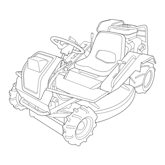
Page 18: Controls And Components
Controls and Components Name and Function of Controls Fuel Filler Cap Seat Steering Wheel Front Cover Fuel Cock Rear Tire Forward Front Tire Rear Cover Cutting Blade Shield 5331M-0201-011E... - Page 19 7 Cutting Height Adjust ..Cutting height adjust lever is used to adjust the cutting Lever height. There are 5 steps on CM141 and any height between 0 and 80mm without steps on CM142. 8 Cutting Rotary Clutch ..Cutting rotary clutch lever is used to start or stop rotating Lever cutting rotary.
-
Page 20: Specifications
Specifications Product Specifications · Use this product properly after understanding its specifications thoroughly. Model and Type CM141 CM142 Machine Mass Mowing Rate 4500 Overall Length 1820 Overall Width Overall Height Wheelbase 1230 Front Tread Rear Ground Clearance Model Robin EX40DS... -
Page 21: Contents Of Tool Bag
Operator's Manual for the Engine Engine Service Tool for Servicing Engine Plate for pushing Quick Reference Guide for Rear Cover Option Type Product Name Note Grass Catcher Sweeper 38 With model-specific hitch* Specify the one for CM141/142 when ordering. -12-... -
Page 22: Operation
Operation Preparation Pre-start up Inspection • Always perform a pre-startup inspection. If machine needs repair, service it before use. • Fire hazard: clean machine of cut grass and similar materials. Cut grass that is accumulated on the machine can catch fire. Always perform an inspection before use. -
Page 23: Adjusting Seating Position
Operation Adjusting Seating Position • Beware of pinch points when adjusting seating position. • After adjusting seat, try moving seat back and forth and up and down to make sure it is securely locked in its position. Lift seat up. Seat 5331M-0401-020E Loosen bolts and slide seat forward or... -
Page 24: Driving
This machine cannot perform adequately above that altitude. Using this machine under such conditions may result in an accident or cause damage to machine. If you need to use this machine above that altitude, contact your CANYCOM representative. -15-... - Page 25 Operation Open fuel cock. Fuel Cock Open 5331M-0402-141E Make certain brake pedal is depressed and Parking Brake Lever locked. If it is not, depress brake pedal and pull lock lever to lock it. NOTE • Safety feature: engine cannot be started unless brake pedal is depressed.
- Page 26 Operation Move throttle lever slightly toward [HI (fast)] position. Throttle Lever 53314M-0402-040E Move choke lever to [Close] position. Choke Knob Close 5331M-0402-151E Insert ignition key into main switch. Turn key to [ (start)] position to start engine. Release key immediately after Start engine starts.
-
Page 27: Driving
Operation 10. Move choke lever back to [Open] position. 11. Run engine without load for about 2 minutes to warm up. Choke Knob NOTE • Drive machine gently in the first week (40 to 50 hours) of operation after purchase for Open breaking-in. - Page 28 Operation M a k e c e r t a i n o f t h e s a f e t y o f y o u r surroundings. Move the throttle lever toward [HI (fast)] position to increase engine speed. Throttle Lever 53314M-0402-170E Depress brake pedal to release brake pedal...
-
Page 29: Stopping
Operation Stopping • Always park on a firm, level place. Never park on a potentially dangerous place. • Do not hold drive lever in a position other than neutral and depress brake pedal simultaneously. HST may be damaged. Gradually return drive lever to [ (neutral)] to slow down. -
Page 30: Locking Differential (Differential Lock Model Only)
Operation Locking Differential (Differential Lock Model Only) Differential can be locked to minimize slipping on slippery surface. • Always stop machine to operate differential lock lever. Operating differential lock lever while machine is in motion can damage differential. • Keep differential lock in [OFF] position under normal running condition. Differential may be damaged. -
Page 31: Parking
Operation Parking • Always park on a firm, level place. Never park on a potentially dangerous place. • Avoid parking on a slope. Never park on a slope with an incline of 10 degrees or steeper. If it is absolutely necessary to park machine on a slope less than 10 degrees, make certain to apply parking brake firmly and block wheels with chocks. - Page 32 Operation Turn main switch to [ (off)] to stop engine. Remove ignition key. Main Switch 5331M-0402-131E -23-...
-
Page 33: Working
• Cutting Height indicated on the side of the adjust lever is for reference purpose only; actual cutting height may vary due to the condition of ground or brush, and other factors. Adjusting Cutting Height (CM141) Move cutting height adjust lever to a desired Cutting Height position. -
Page 34: Cutting
Operation Cutting • Never place any part of body under cutting blade shield. • Do not allow bystanders to come near machine when cutting. • Rotating cutting blades can throw stones or debris and cause injuries and damages to nearby people, animals, crops, buildings, automobiles, etc. Pay attention to the safety of surroundings and plan ahead when cutting. - Page 35 Operation • Wash cutting blade (page 58) after every use. • Do not work on a slippery surface. • When working in a dusty area, clean air cleaner element twice a day. Dirty air cleaner element results in poor starting, poor performance, or short life. •...
- Page 36 Operation Move cutting height adjust lever to a desired height. Cutting Height Adjust Lever 5331M-0403-010E Move rotary clutch lever to [ON] to start cutting blade. Cutting Rotary Clutch Lever 5331M-0403-030E Drive machine forward to cut. NOTE • When cutting with this machine for the first time, start on a flat surface.
- Page 37 Operation Move cutting rotary clutch lever to [OFF] to stop cutting blade. Cutting Rotary NOTE Clutch Lever • Moving cutting rotary clutch lever to [OFF] applies brake on cutting blade to stop. 5331M-0402-020E M o v e c u t t i n g h e i g h t a d j u s t l e v e r t o [Transport].
-
Page 38: Maintenance
Every 100 hours Replace fuel strainer Every 200 hours Replace air cleaner element Every 200 hours (contact Canycom representative for placement) Check and adjust spark plug gap Every 200 hours (contact Canycom representative for placement) Check and adjust tappets Every 300 hours (do more frequently in dusty place) -
Page 39: Chassis
• Perform a pre-startup inspection (PSI) before each use, a monthly inspection once a month, and a yearly inspection once a year. • Some maintenance procedures described below may require special knowledge or tools and instruments. Contact your CANYCOM representative to perform such procedures. Schedule... - Page 40 Maintenance Schedule Item Description Note Shall be free of cracks, deformation, or √ √ corrosion. Chassis, Fastening bolts or nuts shall not be loose or Frame √ √ √ missing. Shall be free of cracks, deformation, or √ √ corrosion. Doors and lids shall open, close, and lock √...
-
Page 41: List Of Fluids And Lubricants
Maintenance List of Fluids and Lubricants Item Schedule Grade Cap. Fuel As needed. Automotive Unleaded Gasoline 7.0 L Engine Oil Gasoline Engine Oil Fill API rating: SE or better. Inspect daily. Fill as needed. SAE rating: 10W-30 Change 1.2L Initially - After 20 hours of use. Every 100 hours afterwards. -
Page 42: Greasing Points
Maintenance Greasing Points • Grease regularly. Insufficient greasing may result in seizure or rusting, affecting smooth operation of machine. NOTE • When using a manual grease pump, push handle five to six times. When handle becomes heavy, stop pushing. • When using a pneumatic grease pump, charge for two to three seconds. Greasing Points Location Schedule... -
Page 43: List Of Consumables And Spares
Maintenance List of Consumables and Spares • When replacing consumable or spare, always use CANYCOM genuine part. • Using non-genuine parts may void warranty. Item Part No. Schedule Qty. Engine Air Cleaner Element ZR20B32610H7 Every 200 hours or seasonally. Clean: every 100 hours. - Page 44 Maintenance Item Part No. Schedule Qty. Electrical System Battery 40B19R 37053901000 Replace if defective. Fuse, 15A (Green, Main) 09801003002 Replace if defective. *1 Differential Lock Model 2 Included within set of blades (Iai) -35-...
-
Page 45: Removing And Installing Body Panels
Maintenance Removing and Installing Body Panels • Always stop engine and remove key when removing body panels • Cut or pinch hazard exists when removing or installing body panels; beware of sharp edges and pinch points. • Make certain to reinstall panels after removing for repairs or inspection. Front Cover Remove knob bolt. -
Page 46: Rear Covers
Maintenance Rear Cover Insert key for engine cover into lock and Cover Handle unlock. Lock Pull cover handle to open rear cover. Close cover and lock. Remove key from lock. Check if cover is locked firmly by pressing cover handle. Rear Cover 5331M-0505-030E Rear cover panel can be removed by sliding... -
Page 47: Floor Panel
Maintenance Floor Panel Remove 4 bolts. Bolts Remove upper rear cover. Floor Panel Bolts (right and left) 5331M-0505-060E Cutting Blade Shield Loosen knob bolt and lift blade shield. Tighten knob bolt and fix blade shield firmly. NOTE Blade Sheild • Blade shield can not fully opened when cutting height adjust lever is in [Transport] position. -
Page 48: Engine
Maintenance Engine • Always stop engine and remove ignition key before servicing. • An engine that has been running is very hot. Allow engine to cool before servicing, or severe burns may result. • Keep fire away from machine when servicing. Engine Oil •... - Page 49 Maintenance Visually inspect oil level. Make sure oil level is between upper and lower limits. If it is below lower limit, add oil. Upper Limit Visually inspect condition of oil. If it is too dirty or viscosity is not normal, change oil. Put oil gauge back in place.
-
Page 50: Air Cleaner
Maintenance Air Cleaner • Clean air cleaner element daily. Dirty air cleaner element causes poor starting, reduces engine performance and shortens engine life. • Replace air cleaner element if damaged. Follow the instructions in Operator's Manual for the engine to inspect, clean or change Element Air Cleaner air cleaner element. -
Page 51: Drive Train
Maintenance Drive Train • Stop engine and remove ignition key before servicing drive train. • Allow machine to cool off before servicing. Engine and its ancillaries are very hot after operation and may pose a burn hazard. • Dispose of drained oil properly. Tires •... -
Page 52: Transmission Oil
Maintenance Transmission Oil NOTE • Oil to Use: Page 34. • Oil Capacity: Page 34. Inspecting Oil Level Gauge Park machine on a level ground. Upper Limit Visually inspect amount and condition of oil. Standard Level Check if oil level is between upper and lower Lower Limit limits. -
Page 53: Hst (Hydrostatic Transmission) Fluid
Maintenance HST (Hydrostatic Transmission) Fluid NOTE • To obtain correct reading, check HST fluid level before starting, or wait until HST fluid cools off sufficiently. Hot HST fluid expands in volume and does not provide correct reading. • It is enough if oil level is on [MIN] when oil is sufficiently cool. •... -
Page 54: Drive Belt
A of spring is within the range of 69 mm to 70mm. If it is out of this range, adjust spring with adjust nut. Visually inspect belt. Replace belt if it is damaged. For replacement, contact your CANYCOM representative. V-Belt Install upper rear cover back in place. Spring 5331M-0507-040E... -
Page 55: Parking Brake
Maintenance Parking Brake • Always keep brake adjusted for maximum performance. Improperly adjusted brakes may result in property damage, serious injury, or death. Brake Spring Lock brake pedal with parking brake lock lever. Remove floor panel. Inspect that the strech of spring is 3mm. If it is not, adjust it with adjust nut. -
Page 56: Cutting System
Maintenance Cutting System • Stop engine and remove ignition key when servicing. • Allow machine to cool off before servicing. Engine and its ancillaries are very hot after operation and may pose a burn hazard. Cutting Blades • When a blade is damaged, replace it and the other blade immediately. Always replace blades in pair. - Page 57 • Wear Limit: Up to the solid line in the left figure (should have more than 15mm 5331M-0508-040E clearance between edge of rotor stay and mounting slot.) • Contact your CANYCOM representative for replacement of rotor stay. Mounting, Dismounting Hole Mounting Slot Lug-Hole...
- Page 58 Maintenance Replacing Mounting Slot Open cutting blade shield. Noting the direction of the flat faces on mounting pin, shift blade along mounting slot to remove blade. Flat Faces 5331M-0508-050E Install new mounting pin to blade and shift blade along mounting slot, noting the direction of the flat faces.
-
Page 59: Cutting Rotary Drive Belt
Open rear cover. Move cutting height adjust lever to [5] Adjust Nut position on CM141 or [80] on CM142. Move cutting rotary clutch lever to [ON]. Check V-belt tension. Inspect that the length A of spring is within the range of 112 mm to 113mm. -
Page 60: Cutting Rotary Brake
Start engine. Turn throttle lever to [HI (fast)] to raise engine speed. Move cutting height adjust lever to [5] position on CM141 or [80] on CM142. Turn cutting rotary clutch lever to [ON] to rotate cutting blade. Move cutting rotary clutch lever to [OFF] to observe if cutting blade stops within 5 seconds. - Page 61 5mm when clutch lever is in [OFF] position. Install upper rear cover rear cover back in place. Check if cutting blade stops within 5 seconds again. If it does not, consult with your 5331M-0509-040E CANYCOM representative. 5323M-0509-040E -52-...
-
Page 62: Electrical System
Maintenance Electrical System • Always stop engine and remove ignition key when servicing electrical system. • Never attempt to service electrical system with wet hands. Never touch electrical terminals. There is a risk of electric shock. Battery • Never charge battery when the fluid level is below "LOWER" level line. Charging battery with insufficient fluid may shorten battery life or cause an explosion. - Page 63 Maintenance • Never fill battery fluid beyond "UPPER" level line. Battery fluid may spill and cause damage to machine or injury to person. • Follow battery charger user's manual when charging. Inspecting Park machine on level ground. Remove front cover. 5331M-0509-010E Visually inspect that battery fluid level is between "UPPER"...
-
Page 64: Fuse
Maintenance Remove filler caps. Filler Cap Fill distilled water to "UPPER" level line. Put filler caps back in place. Install battery back in place. Install positive (+) cable. 10. Install negative (-) cable. 11. Install mounting plate back in place. 12. -
Page 65: After Use Care
• Turn cutting rotary clutch to [ON] only when cleaning. Keep it in [OFF] position all the other times. Park machine. Hose Fitting Set cutting height to 3 or 4 on CM141 or about [50] on CM142. Flip seat. Connect hose to hose fitting on mower deck. -
Page 66: After Normal Use
Maintenance NOTE • Do not set cutting height too low. It may hit ground • Work on level ground without any stones. • Use hose with 15mm or 18mm of inner diameter. After Normal Use • Fire hazard; clean machine of cut grass and similar material after use. Cut grass that is accumulated on the machine can catch fire. -
Page 67: After Cold Weather Use
Maintenance After Cold Weather Use • Fire hazard; clean machine of cut grass and similar material after use. Cut grass that is accumulated on the machine can catch fire. • Do not wash engine or control panel with running water; water may enter inside and cause rust or damage. -
Page 68: Storage
Maintenance Storage • Fire hazard; do not store machine where there is a possiblity of ignition. • Do not wash engine or control panel with running water; water may enter inside and cause rust or damage. • Clean machine before storage; dirt or foreign objects may freeze and cause damage. -
Page 69: Troubleshooting
Troubleshooting chart below. If the malfunction or abnormal condition is not listed in the chart, or the suggested measure does not solve the problem, consult with your CANYCOM representative. • Some corrective measures listed below require special knowledge and/or equipment. - Page 70 Excessive load Reduce load. (by Poor power or acceleration adjusting cutting height) Other (other than the →Please contact above). your CANYCOM representative. →Please contact Irregular noise or your CANYCOM vibration from or representative. around the engine →Please contact Excessive oil...
- Page 71 V-belt is loose. →Adjust V-belt. Page 47 is operated. Other (other than the →Please contact above). your CANYCOM representative. HST is out of neutral. →Please contact Machine moves when Drive your CANYCOM drive lever is in neutral Train representative.
- Page 72 Abnormal vibration by cutting blade. foreign object. occurs when cutting Other (other than the →Please contact blade is rotated. above). your CANYCOM representative. Cutting Grass is wet. →Cut when grass is dry. System Grass is too long. →Cut in several steps at different heights.
- Page 73 Troubleshooting Area Malfunction Possible Cause Corrective Measure Ref. Cutting height is too →Raise cutting height. low. Work site has →Raise cutting height. Cutting blade cuts into undulations. ground. Cutting blade (knives →Replace. or stay) is bent. Cutting Engine speed is too low. →Raise engine speed. System Driving speed is too →Drive slow.
-
Page 74: Transporting
Transporting Hauling Loading and Unloading • Park transporter (truck) on a level ground and apply parking brake. Always use chocks to secure wheels. • Do not allow bystandars to come close to machine or transporter when loading or unloading machine. •... -
Page 75: Hoisting
Transporting Turn throttle lever to [Low], set cutting height adjuster lever to [Transport], and drive machine slowly forward onto loading deck. Park machine according to the instructions in "Parking" (Page 24). Tie tmachine with rope or tie-down belts and secure it onto loading deck of transporter securely. Hoisting •... -
Page 76: Manual Transfer Lever
Transporting Manual Transfer Lever • Do not use manual transfer lever except in an emergency situation. Always stop engine and remove ignition key before push machine by hand. • Always push machine by two persons, one to operate steering wheel and the other to operate manual transfer lever. - Page 77 NOISE LEVEL Model Engine Type Type Speed rpm CM141/CM142 Robin EX40DS 3600 rpm 100 dB (A) NOISE LEVEL evaluated based on factory standard. VIBRATION Vibration Engine Steering Model Mower Blade Steering Rated revolution wheel (cen- Seat Clutch wheel (side) ter) 27.5 m/s...
Need help?
Do you have a question about the CM141 and is the answer not in the manual?
Questions and answers