
Related Manuals for Proliphix IMT Series


Summary of Contents for Proliphix IMT Series
-
Page 1: Installation Guide
Proliphix Internet Managed Thermostat (IMT) Installation Guide Release 1.0 Part No. 600-03100-000, Rev. 2 June 2010... - Page 2 3 years for the IMT series thermostats from the date of purchase. Proliphix shall not be liable to honor the terms of this warranty if the product has been used in any other application other than that for which it was intended, or if it has been subjected to misuse, accidental damage, acts of God, modification, or improper installation procedures.
- Page 3 Return Material Authorization (RMA) number. Products may be returned for credit, exchange, or service with a Proliphix RMA number and with proof of purchase. Enclose a note explaining the symptoms of the problem, stating the RMA number, and the name, address and phone number of the company or individual contact.
- Page 4 Proliphix Internet Managed Thermostat (IMT) Installation Guide, Release 1.0 Part No. 600-03100-000, Rev. 2...
-
Page 5: Installing The Thermostat
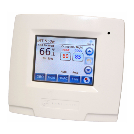
Beta Draft Confidential Overview The Proliphix Internet Managed Thermostat (IMT) provides a rich set of innovative features including the ability to configure settings through a graphical interface either locally or from any remote location. The “c” model suffix thermostats can be connected via secure wired Ethernet to a home, small business, or light commercial data network, while the "w"... -
Page 6: Installation Guidelines
HVAC system and damage the thermostat, and therefore void the warranty. All wiring must conform to local codes and ordinances. The distance between CAT5/CAT5E/CAT6 cables and HVAC cables should be a minimum of one inch. Proliphix Internet Managed Thermostat (IMT) Installation Guide, Release 1.0 Part No. 600-03100-000, Rev. 2... -
Page 7: Before You Begin
Beta Draft Confidential Before you Begin Before you Begin If you are removing an existing thermostat, Proliphix recommends that you label each connection as you remove the wiring. You will use these same wires (and labels) when you connect the IMT. See... -
Page 8: Wiring The Base Plate Terminals
2nd stage Heat RVS O/B RVS O/B Cool 1st stage Cool 1st stage 1st stage Compressor Compressor not used 2nd stage Cool not used 2nd stage Compressor Proliphix Internet Managed Thermostat (IMT) Installation Guide, Release 1.0 Part No. 600-03100-000, Rev. 2... - Page 9 Source HVAC System The wiring colors shown above are examples of commonly used colors and may differ depending on the HVAC wiring that is used. Note Proliphix Internet Managed Thermostat (IMT) Installation Guide, Release 1.0 Part No. 600-03100-000, Rev. 2...
- Page 10 Source HVAC System The wiring colors shown above are examples of commonly used colors and may differ depending on the HVAC wiring that is used. Note Proliphix Internet Managed Thermostat (IMT) Installation Guide, Release 1.0 Part No. 600-03100-000, Rev. 2...
-
Page 11: Configuring Remote Sensors
Loosen the terminal post screw used to secure the wires. Insert the wire straight down into the square hole and secure the corresponding screw to the wire. To avoid damage to the Proliphix base plate, stop unscrewing the terminal post screws when you feel a slight stop or resistance. -
Page 12: Connecting Cat5/Cat5E/Cat6 Wiring For Ethernet Networks To Imt550C Thermostats
Figure 4 and match the label number to the Proliphix base plate number for CAT5/CAT5E/CAT6 color coding. If the other end of the CAT5/CAT5E/CAT6 cable is connected to a Proliphix EPA-20/60 Ethernet Power Adapter, follow the wiring scheme for T568A. Note All wiring must conform to local codes and ordinances. -
Page 13: Configuring Auxiliary Relay And Sensors
Port 1 Auxiliary Relay Normally Closed COM1 Port 1 Auxiliary Relay Common Port 2 Auxiliary Relay Normally Open Port 2 Auxiliary Relay Normally Closed COM2 Port 2 Auxiliary Relay Common Proliphix Internet Managed Thermostat (IMT) Installation Guide, Release 1.0 Part No. 600-03100-000, Rev. 2... -
Page 14: Configuring Auxiliary Relay Jumpers
Figure 5 Auxiliary Relays with Jumpers When the jumpers are removed (see Figure 6), the Auxiliary Relays are configured to use an external power source. Figure 6 Auxiliary Relays without Jumpers Proliphix Internet Managed Thermostat (IMT) Installation Guide, Release 1.0 Part No. 600-03100-000, Rev. 2... - Page 15 If Heat Pump is a model which activates the reversing valve (O) for cool mode. Aux Heat is the last stage whether you have a single or dual stage heat pump. Note Proliphix Internet Managed Thermostat (IMT) Installation Guide, Release 1.0 Part No. 600-03100-000, Rev. 2...
-
Page 16: Mounting The Thermostat Into The Base Plate
The power settings determine which HVAC power source (RH or RC) is configured to turn on each HVAC system (cool, heat, and fan). Most applications use only RH power. The Proliphix thermostat is shipped from the factory with the RH and RC jumpered together. - Page 17 Proliphix Ethernet Power Adapters (EPA) are multi-port power injectors capable of supplying power to either two (EPA-20) or six (EPA-60) Proliphix Network Thermostats. (IMT550c and IMT550w) 24VAC is power from the HVAC system which requires RH and C to both be connected to provide power to the thermostat.
-
Page 18: Verifying The Thermostat's Operating Status
Logging In to the Thermostat Log in to the TMI as the Administrator as follows: Enter the username: admin. Enter the password: admin (default). Proliphix Internet Managed Thermostat (IMT) Installation Guide, Release 1.0 Part No. 600-03100-000, Rev. 2...
Need help?
Do you have a question about the IMT Series and is the answer not in the manual?
Questions and answers