Advertisement
Table of Contents
- 1 Installing the Thermostat
- 2 Required Tools
- 3 Installation Guidelines
- 4 Before You Begin
- 5 Installing and Wiring the Thermostat
- 6 Installing the Base Plate
- 7 Wiring the Base Plate Terminals
- 8 Fuel Burner HVAC
- 9 Mounting the Thermostat into the Base Plate
- 10 Verifying the Thermostat's Operating Status
- 11 Testing the Heat Controls
- 12 Testing the Cool Controls
- 13 Testing the Fan Operation
- 14 Troubleshooting
- Download this manual
Advertisement
Table of Contents

Subscribe to Our Youtube Channel
Summary of Contents for Proliphix Thermostat
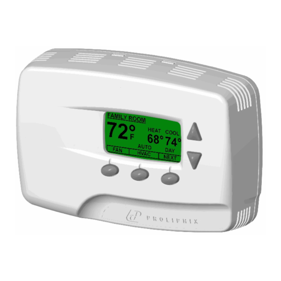
- Page 1 Proliphix Thermostat Installation Guide Release 1.0 Part No. 600-01000-100 April 2006...
- Page 2 (including property and economic) of any kind arising from the sale and use of this equipment. Proliphix is not liable for any claim made by a third party or made by a purchaser for a third party.
- Page 3 Proliphix. Return shipping charges following repair of items under warranty shall be paid by Proliphix via standard ground carrier. In the event that repairs are found to be non-warranty, return shipping charges will be paid by the purchaser.
- Page 4 Beta Draft Confidential Proliphix Thermostat Installation Guide, Release 1.0 Part No. 600-01000-100...
-
Page 5: Installing The Thermostat
Preventing electrostatic discharge (ESD) — Static electricity may cause damage to the components on the thermostat’s circuit module. Do not remove the Caution thermostat from the protective bag until you are ready to install the thermostat. Required Tools The following tools are required to install the Proliphix thermostat: #1 or #2 Phillips head screwdriver. -
Page 6: Installation Guidelines
If you are replacing an existing thermostat, mount the Proliphix thermostat in the same location as the thermostat in which you are replacing. Install the thermostat on an inside wall, about 5 feet (1.5m) above the floor, and in a room that is used often. -
Page 7: Before You Begin
Disconnect each wire. Label the wires with the terminal designation from the existing thermostat. Place the label about 1/2” away from the end of the wire to allow for stripping of the ends. Note: If this is a new installation, obtain the wire designations from the HVAC installer. -
Page 8: Wiring The Base Plate Terminals
For “h” thermostat models only, the 24VAC common must be in the same AC phase as the 24VAC source (RH or RC). If the thermostat is connected to RH only, or RH and RC then C must be the RH common. - Page 9 Applies to “h” models only Table 1 to match the letter of your existing thermostat wire to the corresponding terminal letter on the Proliphix base plate. Strip the wire insulation 3/8” (9.5 mm) from the wire ends. Verify that the wire ends are straight.
- Page 10 For “h” thermostat models only, the 24VAC common must be in the same AC phase as the 24VAC source (RH or RC). If the thermostat is connected to RH only, or RH and RC then C must be the RH common. If the thermostat is connected to RC only then C must be the RC common.
- Page 11 Analog sensors convert temperature measurements as Fahrenheit degrees to a voltage which can be sensed by the thermostat. Analog sensors are active devices which require power from the thermostat. The Analog sensor is polarized and must be connected as shown in...
- Page 12 Figure 3 and match the label number to the Proliphix base plate number for CAT5/CAT5E/6 color coding. If the other end of the CAT5/CAT5E/6 cable is connected to a Proliphix EPA-20/60 Ethernet Power Adapter, follow the wiring scheme for T568A. Note All wiring must conform to local codes and ordinances.
- Page 13 Table 4 T568A and T568B Pinout Assignments Pin Number T568A Wire Color T568B Wire Color Green/White Orange/White Green Orange Orange/White Green/White Blue Blue Blue/White Blue/White Orange Green Brown/White Brown/White Brown Brown Proliphix Thermostat Installation Guide, Release 1.0 Part No. 600-01000-100...
-
Page 14: Mounting The Thermostat Into The Base Plate
The power settings determine which HVAC power source (RH or RC) is configured to turn on each HVAC system (cool, heat and fan). Most applications use only RH power. The Proliphix thermostat is shipped from the factory with the “RH Only” configuration. -
Page 15: Verifying The Thermostat's Operating Status
Beta Draft Confidential Installing and Wiring the Thermostat Figure 5 Thermostat Jumper Locations Prior to mounting the thermostat into the base plate, verify that the jumpers on the thermostat are configured for your application (see Table To mount the thermostat into the base plate:... -
Page 16: Testing The Cool Controls
Press Fan. A menu list appears. Use the Up and Down arrows on the right side of the panel to select On. Press Select. The fan relay should click and the fan should turn on. Proliphix Thermostat Installation Guide, Release 1.0 Part No. 600-01000-100... -
Page 17: Troubleshooting
If using PoE to power your thermostat: Verify that jumper J3 is not connected to both pins (Out position). Verify the PoE equipment is sending power to the thermostat. See your PoE equipment documentation. Verify that Ethernet wiring is securely attached to terminal screws. - Page 18 Beta Draft Confidential Installing and Wiring the Thermostat Proliphix Thermostat Installation Guide, Release 1.0 Part No. 600-01000-100...


Need help?
Do you have a question about the Thermostat and is the answer not in the manual?
Questions and answers