Icom IC-F5062 Instruction Manual
Vhf mobile transceivers/ uhf mobile transceivers
Hide thumbs
Also See for IC-F5062:
- Instruction manual (24 pages) ,
- Operating manual (50 pages) ,
- Servise manual (50 pages)

Related Manuals for Icom IC-F5062


Summary of Contents for Icom IC-F5062
- Page 1 INSTRUCTION MANUAL VHF MOBILE TRANSCEIVERS iF5062 iF5062D UHF MOBILE TRANSCEIVERS iF6062 iF6062D...
-
Page 2: Explicit Defenitions
If disregarded, inconvenience only. No risk NOTE of personal injury, fire or electric shock. Icom, Icom Inc. and Icom logo are registered trademarks of Icom Incorporated (Japan) in Japan, the United States, the United Kingdom, Germany, France, About e-marking: Detailed installation notes for Icom Spain, Russia, Australia, New Zealand, and/or other countries. -
Page 3: Precautions
The radio will become hot when operat- CAUTION: NEVER expose the radio to rain, snow or ing continuously for long periods. any liquids. Use Icom microphones only (supplied or optional). Other manufacturer’s microphones have different pin assignments, and may damage the radio. -
Page 4: Table Of Contents
TABLE OF CONTENTS IMPORTANT ................i 3 CONNECTION AND MAINTENANCE ....14−18 EXPLICIT DEFENITIONS ............. i ■ Rear panel connection ..........14 VOICE CODING TECHNOLOGY .......... i ■ Supplied Accessories ..........16 PRECAUTIONS ..............ii ■ Mounting the transceiver ..........16 TABLE OF CONTENTS ............iii ■... -
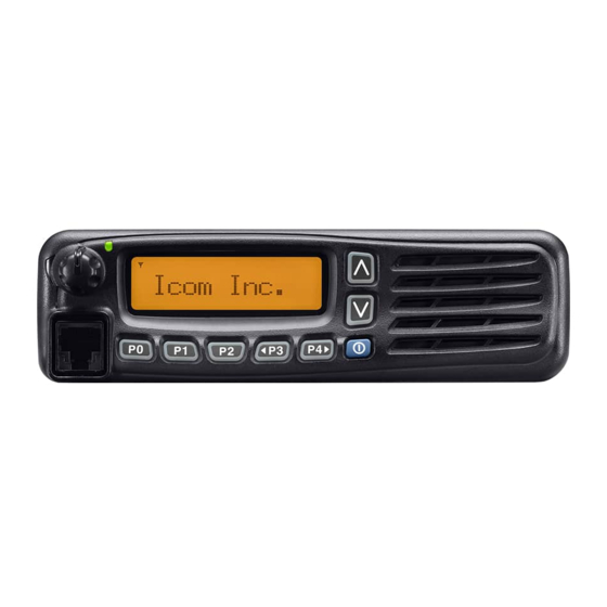
Page 5: Panel Description
PANEL DESCRIPTION ■ Front panel Function display (p. 2) Speaker I c o m I n c . q AF VOLUME CONTROL KNOB [VOL] y MICROPHONE CONNECTOR Rotate to adjust the desired audio output level. Connect the supplied or optional microphone. •... -
Page 6: Function Display
PANEL DESCRIPTION ■ Function display u CALL CODE MEMORY INDICATOR ➥ Displayed when the call code memory is selected. ➥ Displayed when a phone call is received.* I c o m I n c . i SCROLL INDICATOR Displayed when the SDM, includes more than 12 charac- ters, is selected during the received message selection mode* o SDM INDICATOR... -
Page 7: Programmable Function Keys
[P0], [P1], [P2], [P3] and [P4] programmable function keys. Push this key, then select the desired zone using [CH Up]/ [CH Down]. Consult your Icom dealer or system operator for details con- cerning your transceivers programming. What is “zone”?—The desired channels are assigned If the programmable function names are bracketed in the fol- into a zone according to the intended use for grouping. - Page 8 PANEL DESCRIPTION SCAN ADD/DEL (TAG) KEY MONI (AUDI) KEY ➥ Push to add or delete the selected channel to/from the ➥ Push to mute and release the CTCSS (DTCS) or 2-Tone scan group. squelch mute. Open any squelch/deactivate any mute 1.
- Page 9 PANEL DESCRIPTION RX SPEAKER KEY TONE/RAN CH SELECT KEY Push to turn the RX speaker function ON or OFF. ➥ While in analog mode operation, push to enter the con- When the RX speaker function is turned ON, the received tinuous tone channel selection mode.
- Page 10 PANEL DESCRIPTION TALK AROUND KEY EMERGENCY KEY Push to turn the talk around function ON and OFF. Hold down for a preset time period to transmit the emergency • The talk around function equalizes the transmit frequency to the call. receive frequency for transceiver-to-transceiver communication.
-
Page 11: Panel Description
PANEL DESCRIPTION TX CODE CHANNEL UP/DOWN KEYS USER SET MODE KEY Push to select a TX code channel directly. ➥ Hold down for 1 second to enter user set mode. • During in the user set mode, push this key to select an item that is enabled by your dealer, and change the value or condition by SCRAMBLER/ENCRYPTION KEY pushing [CH Up] or [CH Down]. -
Page 12: Basic Operation
BASIC OPERATION ■ Turning power ON ■ Channel selection q Hold down [ ] for 1 second to turn the power ON. Several types of channel selections are available. Methods w If the transceiver is programmed for a start up password, may differ according to your system set up. -
Page 13: Call Procedure
BASIC OPERATION ■ Call procedure ■ Receiving and transmitting When your system employs tone signaling (excluding CTCSS Receiving: and DTCS), a call procedure may be necessary prior to voice q Hold down [ ] for 1 second to turn the power ON. transmission. -
Page 14: D Transmitting Notes
BASIC OPERATION ■ Receiving and transmitting (Continued) D Transmitting notes D TX code channel selection • Transmit inhibit function If the transceiver has [TX Code CH Select] assigned to it, the indication can be toggled between the operating channel The transceiver has several inhibit functions which restrict transmission under the following conditions: number (or name) and TX code channel number (or name). -
Page 15: D Dtmf Transmission
BASIC OPERATION D TX code number edit (PMR operation only) If the transceiver has [TX Code CH Select] or [TX Code USING [TX CODE ENTER] KEY: Enter] assigned to it, TX code contents can be edited within q Push [TX Code Enter] to enter the TX code edit mode. the allowable digits. -
Page 16: User Set Mode
BASIC OPERATION ■ User set mode ■ Scrambler function The User Set mode allows you to set seldom-changed set- The voice scrambler function provides private communication tings. If the transceiver has [User Set Mode] assigned to it, between stations. All versions have a built-in frequency inver- you can customize the transceiver operation to suit your pref- sion type scrambler;... -
Page 17: Emergency Transmission
BASIC OPERATION ■ Emergency transmission ■ Priority A channel selection When [Emergency] is pushed for the specified time period, When one of the following operations is performed, the trans- an emergency signal is automatically transmitted. (p. 6) ceiver selects the Priority A channel automatically. When [Emergency] is pushed for the specified time period, •... -
Page 18: Connection And Maintenance
CONNECTION AND MAINTENANCE ■ Rear panel connection D For mobile operation ANTENNA CONNECTOR D-Sub 25-pin Antenna Connects to an antenna. Contact your deal- Connect an external unit. er about antenna selection and placement. EXTERNAL SPEAKER JACK Optional Connect a 4–8 ø external speaker. speaker Microphone R CAUTION! NEVER... - Page 19 CONNECTION AND MAINTENANCE ■ Rear panel connection (Continued) D For base station operation To antenna Microphone ANTENNA CONNECTOR EXTERNAL SPEAKER JACK DC power IGNITION LEAD Connect a 4–8 ø supply 13.2 V D-Sub 25-pin external speaker. Connect an external unit. DC POWER to an Optional speaker...
-
Page 20: Supplied Accessories
CONNECTION AND MAINTENANCE ■ Supplied Accessories ■ Mounting the transceiver The universal mounting bracket supplied with your trans- Microphone Microphone hanger Microphone ceiver allows overhead mounting. and screw set hanger cable • Mount the transceiver securely with the 4 supplied screws to a thick surface which can support more than 1.5 kg. -
Page 21: Antenna
CONNECTION AND MAINTENANCE ■ Antenna ■ Cleaning A key element in the performance of any communication sys- If the transceiver becomes dusty or dirty, wipe it clean with a tems is an antenna. Contact your dealer about antennas and soft and dry cloth. the best places to mount them. -
Page 22: Options
DTMF code transmission only. performance when used with an Icom transceiver. • SM-25 desktop microphone Icom is not responsible for the destruction or damage to an • SP-22/SP-30/SP-35/SP-35L external speakers Icom transceiver in the event the Icom transceiver is used Input impedance : 4 ø... -
Page 23: Country Code List
COUNTRY CODE LIST • ISO 3166-1 Country Codes Country Codes Austria Liechtenstein Belgium Lithuania Bulgaria Luxembourg Croatia Malta Czech Republic Netherlands Cyprus Norway Denmark Poland Estonia Portugal Finland Romania France Slovakia Germany Slovenia Greece Spain Hungary Sweden Iceland Switzerland Ireland Turkey Italy United Kingdom... - Page 24 < Intended Country of Use > A-6566D-1EU-t Printed in Japan © 2007–2015 Icom Inc. 1-1-32 Kamiminami, Hirano-ku, Osaka 547-0003, Japan Printed on recycled paper with soy ink.
Need help?
Do you have a question about the IC-F5062 and is the answer not in the manual?
Questions and answers