Icom IC-F5061 Instruction Manual
Vhf mobile transceiver; uhf mobile transceiver
Hide thumbs
Also See for IC-F5061:
- Servise manual (50 pages) ,
- Service manual (6 pages) ,
- Price list (158 pages)

Subscribe to Our Youtube Channel
Related Manuals for Icom IC-F5061


Summary of Contents for Icom IC-F5061
- Page 1 INSTRUCTION MANUAL VHF MOBILE TRANSCEIVER iF5061/D iF5063 UHF MOBILE TRANSCEIVER iF6061 iF6061D/D-L iF6063/D iF6067D...
-
Page 2: Explicit Defenitions
Ask your dealer for details. Icom, Icom Inc. and the Icom logo are registered trademarks of Icom Incor- porated (Japan) in Japan, the United States, the United Kingdom, Germany, France, Spain, Russia and/or other countries. -
Page 3: Precautions
CAUTION! Changes or modifications to this transceiver, not CAUTION: NEVER expose the transceiver to rain, expressly approved by Icom Inc., could void your authority to operate this transceiver under FCC regulations. snow or any liquids. the specified microphone only. Other microphones have different pin assignments and may damage the transceiver. -
Page 4: Voice Coding Technology
FCC INFORMATION VOICE CODING TECHNOLOGY The AMBE+2™ voice coding Technology embodied in this • FOR CLASS B UNINTENTIONAL RADIATORS: product is protected by intellectual property rights including This equipment has been tested and found to comply with patent rights, copyrights and trade secrets of Digital Voice the limits for a Class B digital device, pursuant to part 15 of Systems, Inc. -
Page 5: Table Of Contents
TABLE OF CONTENTS IMPORTANT ................i 3 CONNECTION AND MAINTENANCE ....15–18 EXPLICIT DEFENITIONS ............. i ■ Rear panel connection ..........15 PRECAUTIONS ..............ii ■ Supplied Accessories ..........16 VOICE CODING TECHNOLOGY ........iii ■ Mounting the transceiver ..........17 FCC INFORMATION ............iii ■... -
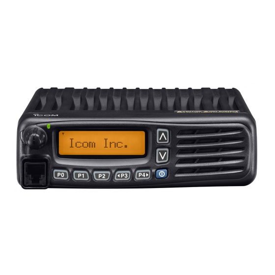
Page 6: Panel Description
PANEL DESCRIPTION ■ Front panel Function display (p. 2) Speaker I c o m I n c . q AF VOLUME CONTROL KNOB [VOL] y MICROPHONE CONNECTOR Rotate the knob to adjust the desired audio output level. Connect the supplied or optional microphone. •... -
Page 7: Function Display
PANEL DESCRIPTION ■ Function display u CALL CODE MEMORY INDICATOR ➥ Appears when the call code memory is selected. ➥ Appears when a phone call is received.* I c o m I n c . i SCROLL INDICATOR Appears when the SDM, includes more than 12 charac- ters, is selected during the received message selection mode* q SIGNAL STRENGTH INDICATOR... -
Page 8: Programmable Function Keys
[P0], [P1], [P2], [P3] and [P4] programmable function keys. Push this key, then select the desired zone using [CH Up]/ [CH Down]. Consult your Icom dealer or system operator for details con- cerning your transceivers programming. What is “zone”?— Selected channels are assigned to a zone according to how they are to be used in a group. - Page 9 PANEL DESCRIPTION SCAN ADD/DEL (TAG) KEY MONI (AUDI) KEY ➥ Push to add the channel to, or delete it from, the current ➥ Push to mute and release the CTCSS (DTCS) or 2-tone scan group. squelch mute. Open any squelch/deactivate any mute 1.
- Page 10 PANEL DESCRIPTION RX SPEAKER KEY TONE/RAN CH SELECT KEY Push to turn the RX speaker function ON or OFF. ➥ While in analog mode operation, push to enter the con- When the RX speaker function is turned ON, the received tinuous tone channel selection mode.
- Page 11 PANEL DESCRIPTION WIDE/NARROW KEY EMERGENCY KEY Push to toggle the IF bandwidth between wide and narrow. Push and hold to transmit the emergency call. (Analog or mixed mode operation only) • The emergency call transmits with beeps; the display does not change.
-
Page 12: Panel Description
PANEL DESCRIPTION TX CODE CHANNEL UP/DOWN KEYS USER SET MODE KEY Push to select a TX code channel directly. ➥ Push and hold for 1 sec. to enter user set mode. • During user set mode, push this key to select an item that is enabled by your dealer, and change the value or condition using SCRAMBLER/ENCRYPTION KEY [CH Up]/[CH Down]. -
Page 13: Basic Operation
BASIC OPERATION ■ Turning power ON ■ Channel selection q Push and hold [ ] for 1 sec. to turn the power ON. Several types of channel selections are available. Methods w If the transceiver is programmed for a start up password, may differ according to your system set up. -
Page 14: Call Procedure
BASIC OPERATION ■ Call procedure ■ Receiving and transmitting When your system employs tone signaling (excluding CTCSS Receiving: and DTCS), a call procedure may be necessary prior to voice q Push and hold [ ] for 1 sec. to turn the power ON. transmission. -
Page 15: D Transmitting Notes
BASIC OPERATION D Transmitting notes D TX code channel selection • Transmit inhibit function If the transceiver has [TX Code CH Select] assigned to it, The transceiver has several inhibit functions which restrict the indication can be toggled between the operating channel transmission under the following conditions: number (or name) and TX code channel number (or name). -
Page 16: D Dtmf Transmission
BASIC OPERATION D TX code number edit (PMR operation only) USING [TX CODE ENTER] KEY: If the transceiver has [TX Code CH Select] or [TX Code Enter] assigned to it, TX code contents can be edited within q Push [TX Code Enter] to enter the TX code edit mode. •... -
Page 17: User Set Mode
BASIC OPERATION ■ User set mode e Push [P0] several times to select the appropriate item. Then, User set mode can be accessed with ‘Power ON’ function. In this case, all set mode items are available. push [Up] or [Down] to set the desired level/condition. User set mode allows you to set seldom-changed settings •... -
Page 18: Scrambler Function
BASIC OPERATION ■ Scrambler function ■ Stun function The voice scrambler function provides private communica- When the specified ID, set as a kill ID, is received, the stun tion between stations. All versions have a built-in frequency function is activated. inversion type scrambler;... -
Page 19: Automatic Key Lock Function
BASIC OPERATION ■ Automatic Key Lock function ■ Power Off Emergency function When [Lock] is assigned to any key and the Automatic Key When [Power OFF Emergency] is assigned to any key, you Lock timer is pre-programmed* by your dealer, the key lock can use the Power OFF Emergency function. -
Page 20: Connection And Maintenance
CONNECTION AND MAINTENANCE ■ Rear panel connection q ANTENNA CONNECTOR w D-Sub 25-pin Connects to an antenna. Connect an exter- Antenna Contact your dealer about nal unit. antenna selection e EXTERNAL Optional speaker placement. SPEAKER JACK Connect a 4–8 ˘ external speaker. -
Page 21: Supplied Accessories
CONNECTION AND MAINTENANCE ■ Supplied Accessories D Self ground type microphone hanger con- Non-self ground type Self ground type nection Microphone Microphone Microphone hanger Microphone Microphone hanger and screw set hanger cable and screw set When the optional microphone (HM-152/T) is used: Mounting bracket DC power cable Function name... -
Page 22: Mounting The Transceiver
CONNECTION AND MAINTENANCE ■ Mounting the transceiver ■ Antenna The universal mounting bracket supplied with your trans- A key element in the performance of any communication ceiver allows overhead mounting. systems is an antenna. Contact your dealer for more infor- •... -
Page 23: Options
Icom transceiver. The 10-keypad of this microphone can be used Icom is not responsible for the destruction or damage to an for the DTMF code transmission only. Icom transceiver in the event the Icom transceiver is used with equipment that is not manufactured or approved by •... -
Page 24: Safety Training Information
48 centimeters separation distance. In order to During transmissions, your Icom radio generates RF energy that can ensure this distance is met, the installation of the antenna must possibly cause interference with other devices or systems. - Page 25 MEMO...
- Page 26 MEMO...
- Page 27 MEMO...
- Page 28 MEMO...
- Page 29 MEMO...
- Page 30 MEMO...
- Page 31 MEMO...
- Page 32 A-6565D-1EX-ya Printed in Japan © 2006–2013 Icom Inc. 1-1-32 Kamiminami, Hirano-ku, Osaka 547-0003, Japan Printed on recycled paper with soy ink.
Need help?
Do you have a question about the IC-F5061 and is the answer not in the manual?
Questions and answers
How do I keep the display light on constantly? Icon ic-f5061d
The instruction manual does not provide information on how to keep the display light on constantly for the Icom IC-F5061. This function may need to be preprogrammed by your dealer.
This answer is automatically generated