Table of Contents
Advertisement
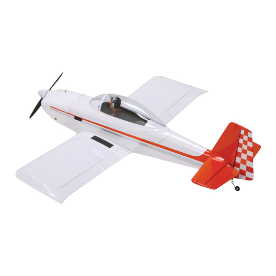
RV-8
Assembly Manual
Specifications
Wingspan: .............................................................. 61 in (1549mm)
Length: ................................................................... 52 in (1321mm)
Wing Area: .........................................................732 sq in ( sq dm)
Weight: ........................................................... 6.5–7 lb (2.9–3.2 kg)
Radio: .................................................. 5-channel with 6–7 servos
Engine: ....... .46–.52 2-stroke, .72–.82 4-stroke, EFL Power 46 EP
RV-8 is a trademark of Van's Aircraft and is used with permission.
Advertisement
Table of Contents

Related Manuals for Hangar 9 RV-8


Summary of Contents for Hangar 9 RV-8
-
Page 1: Specifications
Wing Area: ............732 sq in ( sq dm) Weight: ............6.5–7 lb (2.9–3.2 kg) Radio: ..........5-channel with 6–7 servos Engine: ..46–.52 2-stroke, .72–.82 4-stroke, EFL Power 46 EP RV-8 is a trademark of Van’s Aircraft and is used with permission. -
Page 2: Table Of Contents
Wheel Pants (left and right) 2009 Official Academy of HAN4852 -inch Foam Wheels Model Aeronautics Safety Code ........45 HAN4855 Glow Fuel Tank, 8.8 oz (260cc) Engine Mounting Template ..........47 HAN4858 Pushrods Air Exit Template (EP) ............47 Hangar 9 RV-8 Assembly Manual... -
Page 3: Included Hardware
included Parts and Hardware Wing FuSELAgE Left wing with aileron and flap Fuselage with canopy hatch Right wing with aileron and flap Canopy Clevis aileron & flaps Fuel tank, assembled Pushrod keeper aileron & flaps 3mm x 15mm socket head cap screw cowl &... -
Page 4: Using The Manual
-inch Spinner (DUB290) fuselage, wing panels, rudder and stabilizer for damage. Epoxy brush Felt-tipped pen • Hangar 9 Fuel Filler Dot (Optional) (HAN115) If you find any damaged or missing parts, contact the Hobby knife with #11 blade Hobby scissors place of purchase. -
Page 5: Additional Required Adhesives
Trim seal tool Threadlock available on FS One such as the T-REX, Blade CX2, Blade CP Pro, Hangar 9 P-51 and F-22 PTS. And as always, with the Phillips screwdriver: #2 Hangar Pack, you still get all the same great features that Box end or open end wrench: 10mm (2) you did with the original aircraft. - Page 6 Step 6 Slide the wheel axle through the larger hole in the landing gear. note: There is a right and left landing gear. They cannot be interchanged or installed incorrectly. Hangar 9 RV-8 Assembly Manual...
- Page 7 Apply a drop or two of thin CA to the blind nut to secure it in the wheel pant. Make sure not to get CA in the threads. Hangar 9 RV-8 Assembly Manual...
- Page 8 Step 15 Use a 3mm x 10mm Phillips head screw to secure the wheel pant. The screw threads into the blind nut installed inside the wheel pant. Tighten the screw using a #2 Phillips screwdriver. Hangar 9 RV-8 Assembly Manual...
-
Page 9: Section 2: Servo And Receiver Installation
Prepare the rudder and elevator servos by installing the rubber grommets and brass eyelets as described in the servo or radio manual. note: If you are building the EP version it is not necessary to install the throttle servo. Hangar 9 RV-8 Assembly Manual... - Page 10 Y-harness in the receiver for both the aileron and flap servos. Step 6 Mount the switch harness in the side of the fuselage using the hardware provided with the switch. Hangar 9 RV-8 Assembly Manual...
-
Page 11: Section 3: Rudder Cable Installation
Use a #2 Phillips screwdriver to remove the servo horns cable will then go through the hole of the pre-bent pull-pull from the rudder and elevator servos. fitting then back through the cable crimp. Do not cut the cable at this time. Hangar 9 RV-8 Assembly Manual... - Page 12 While holding the servo arm, pull the cable so you can find the center. Use side cutters to cut the cable in two equal pieces. important: Do not let more than 1/4-inch (6mm) of excess cable exit the crimp. Hangar 9 RV-8 Assembly Manual...
- Page 13 Always adjust both clevises equally to avoid changing the rudder trim. Step 13 Repeat Steps 10 through 12 to connect the opposite cable to the rudder control horn. Hangar 9 RV-8 Assembly Manual...
-
Page 14: Section 4: Elevator/Stabilizer Installation
Use a hobby knife and #11 blade to remove the covering for the two stabilizer tubes in the fuselage on both sides of the fuselage. Step 5 Repeat Steps 2 through 4 to prepare the opposite side of the fuselage for the stabilizer. Hangar 9 RV-8 Assembly Manual... - Page 15 Repeat Steps 6 and 7 to install the remaining stabilizer half before the epoxy begins to cure. Hint: Use rubbing alcohol and a paper towel to remove any excess epoxy from the stabilizer and fuselage before it begins to cure. Hangar 9 RV-8 Assembly Manual...
- Page 16 Use side cutters to remove one arm from a long 180 servo arm. Secure the arm on the servo using the screw that was removed previously. Use a #2 Phillips screwdriver to tighten the screw. Hangar 9 RV-8 Assembly Manual...
- Page 17 Make sure that the bend nearest the pushrod tube is far enough forward that it will not hit the pushrod tube when operating the elevator. Hangar 9 RV-8 Assembly Manual...
-
Page 18: Section 5: 2-Stroke Engine Installation
Hint: Use a #1 Phillips screwdriver or center punch to make an indentation in the firewall so the drill bit does not wander when drilling the holes. Hangar 9 RV-8 Assembly Manual... - Page 19 Hint: Apply a couple drops of medium CA to the barbs of the blind hut before installing. This will help to keep the blind nut secure should you ever need to remove the screw. Hangar 9 RV-8 Assembly Manual...
-
Page 20: Section 6: 4-Stroke Engine Installation
Cut the engine mounting template from Page 47 of the to the former and firewall. manual or use the supplied plywood template. Use low-tack tape to attach it to the front of the firewall as shown. Hangar 9 RV-8 Assembly Manual... - Page 21 3/4-inch socket head screws and four #8 washers. Use a 9/64-inch hex wrench to lightly tighten the screws. You should be able to move the mounts so their position can be fine-tuned for your particular engine. Hangar 9 RV-8 Assembly Manual...
-
Page 22: Section 7: Fuel Tank Installation And Throttle Linkage Connection
Use a pin drill and 5/64-inch (2mm) drill bit to enlarge the firewall after making sure they have threadlock on them to hole that is 1/2-inch (13mm) from the center of the throttle keep them from vibrating loose. servo arm. Hangar 9 RV-8 Assembly Manual... - Page 23 3mm x 3mm setscrew to secure the To Muffler pushrod wire to the pushrod connector. Remember to use threadlock on the setscrew to prevent it from vibrating loose. To Carburetor Vent Line (faces top of fuselage) Clunk Side View Hangar 9 RV-8 Assembly Manual...
- Page 24 Place a piece of foam at the rear of the tank so it will not slide rearward in the fuselage. note: We used a fuel dot so the fuel tank can be filled without the need to remove the cowl. Hangar 9 RV-8 Assembly Manual...
-
Page 25: Section 8: Electric Motor Installation
Use low-tack tape to attach it to the front of the firewall as shown. Step 3 Use a drill and 11/64-inch (4.5mm) drill bit to enlarge the holes for mounting the motor. Hangar 9 RV-8 Assembly Manual... - Page 26 Use a #2 Phillips screwdriver to attach the mount to the operation of the motor. motor using the hardware included with the motor. Make sure to use threadlock on the screws to prevent them from vibrating loose. Hangar 9 RV-8 Assembly Manual...
- Page 27 Use low-tack tape to secure the template to the bottom of the fuselage. Step 12 Carefully fold the template along the fold lines. This will assist in positioning the template on the bottom of the fuselage. Hangar 9 RV-8 Assembly Manual...
- Page 28 #11 blade to cut through the wood on the bottom of the fuselage using the marks on the bottom of the fuselage as a guide. Work slowly to not let the knife slip and cut more than necessary. Hangar 9 RV-8 Assembly Manual...
-
Page 29: Section 9: Cowling And Spinner Installation
Step 3 Slide the propeller adapter on the motor shaft if you are using an electric motor. Hangar 9 RV-8 Assembly Manual... - Page 30 Step 8 Make any necessary cutouts for the needle valve, muffler and cooling outlet for your glow engine installation. Step 7 Attach the spinner cone (not included) using the hardware provided with the spinner. Hangar 9 RV-8 Assembly Manual...
-
Page 31: Section 10: Canopy And Pilot Installation
A razor saw will be required to cut through the foam inside the pilot. Finish up by sanding the bottom of the pilot flat using a sanding bar and medium grit sandpaper. Hangar 9 RV-8 Assembly Manual... -
Page 32: Section 11: Aileron And Flap Servo Installation
Drill bit: 1/16-inch (1.5mm), 5/64-inch (2mm) Step 1 Remove the servo cover for the aileron from the wing panel. Note the location of the servo horn exit on the cover and how it aligns with the control horn. Hangar 9 RV-8 Assembly Manual... - Page 33 Use a pencil to mark the locations for the four servo mounting screws. Sand this end Hangar 9 RV-8 Assembly Manual...
- Page 34 Use a #1 Phillips screwdriver and the screws provided with with the control horn. the servo to secure the servo to the mounting blocks. Hangar 9 RV-8 Assembly Manual...
- Page 35 10-turns on the threaded end of the pushrod wire. note: The heat shrink on the clevises will be tightened after the control throws have been set. Hangar 9 RV-8 Assembly Manual...
- Page 36 Step 21 Make a 90-degree bend in the pushrod made in the previous step. Use a rotary tool and cutoff wheel to trim the pushrod wire 3/8-inch (10mm) from the bend as shown. Hangar 9 RV-8 Assembly Manual...
-
Page 37: Section 12: Wing And Canopy Hatch Installation
Remove the covering on the bottom of the fuselage as well to access the holes for the wing mounting screws. Hangar 9 RV-8 Assembly Manual... - Page 38 Use a 2.5mm ball driver or hex wrench to tighten the 3mm x 20mm socket head screws and 3mm washer that secures the wing to the fuselage. Hangar 9 RV-8 Assembly Manual...
-
Page 39: Section 13: Center Of Gravity
Step 8 Place the canopy hatch on the fuselage. After the first flights, the CG position can be adjusted for your personal preference. Hangar 9 RV-8 Assembly Manual... -
Page 40: Section 14: Control Throws
Hangar 9 RV-8 Assembly Manual... -
Page 41: Section 17: Safety Do's And Don'ts For Pilots
• Elevator and Aileron dual rates should be adjusted for personal feel and also if there is any unusual wind conditions. Hangar 9 RV-8 Assembly Manual... -
Page 42: Section 19: Glossary Of Terms
It is attached to the bottom of the All servo pigtails and switch harness plugs should be fuselage. secured in the receiver. Make sure that the switch harness moves freely in both directions. Hangar 9 RV-8 Assembly Manual... -
Page 43: Section 20: Safety, Precautions And Warnings
Product. This warranty does not cover damage due to improper installation, operation, maintenance, or attempted repair by anyone other than Horizon. Return of any goods by Purchaser must be approved in writing by Horizon before shipment. Hangar 9 RV-8 Assembly Manual... - Page 44 Please call 877-504-0233 or e-mail us at productsupport@ repaired or replaced free of charge. Repair or replacement horizonhobby.com with any questions or concerns regarding decisions are at the sole discretion of Horizon Hobby. this product or warranty. Hangar 9 RV-8 Assembly Manual...
-
Page 45: Instructions For Disposal Of Weee By
For more information about where you can drop off your waste equipment for recycling, please contact your local city office, your household waste disposal service or where you purchased the product. Hangar 9 RV-8 Assembly Manual... -
Page 46: 2009 Official Academy Of Model Aeronautics Safety Code
AMA clubs and individual AMA members, or individual Advisory Committee Document. AMA members. Frequency-management agreements, including an interference test report if the agreement indicates no interference exists, will be signed by all parties and copies provided to AMA Headquarters. Hangar 9 RV-8 Assembly Manual... -
Page 47: Engine Mounting Template
Engine Mounting Template Air Exit Template (EP) Fold Saito & Evolution Power 46 Saito Evolution Fold Hangar 9 RV-8 Assembly Manual... - Page 48 © 2009 Horizon Hobby, Inc. 4105 Fieldstone Road Champaign, Illinois 61822 (877) 504-0233 horizonhobby.com Hangar9.com 14371...
Need help?
Do you have a question about the RV-8 and is the answer not in the manual?
Questions and answers