Table of Contents
Advertisement
Quick Links
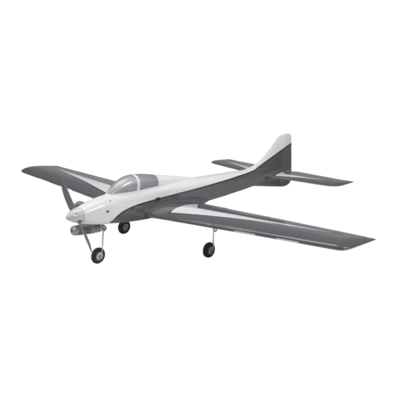
DIRTY BIRDY .60 ARF INSTRUCTION MANUAL
Wingspan: 64.5 in [1640 mm]
Wing Area: 690 in
Wing Loading: 25−28 oz/ft
Length: 56 in [1420 mm]
WARRANTY
Great Planes Model Manufacturing
be free from defects in both material and workmanship at the
date of purchase. This warranty does not cover any component
parts damaged by use or modification. In no case shall Great
Planes' liability exceed the original cost of the purchased kit.
Further, Great Planes reserves the right to change or modify this
warranty without notice.
In that Great Planes has no control over the final assembly or
material used for final assembly, no liability shall be assumed nor
accepted for any damage resulting from the use by the user of
the final user-assembled product. By the act of using the
user-assembled product, the user accepts all resulting liability.
If the buyer is not prepared to accept the liability associated
with the use of this product, the buyer is advised to return
READ THROUGH THIS MANUAL BEFORE STARTING CONSTRUCTION. IT CONTAINS IMPORTANT
INSTRUCTIONS AND WARNINGS CONCERNING THE ASSEMBLY AND USE OF THIS MODEL.
®
Entire Contents © 2011 Hobbico,
Inc. All rights reserved.
2
2
[44.5 dm
]
2
2
[76− 85 g /dm
]
®
Co. guarantees this kit to
Weight: 7.5− 8.5 lb
[3400 −3850 g]
Radio: 4-channel minimum
with 5-7 servos and
standard size receiver
this kit immediately in new and unused condition to the
place of purchase.
To make a warranty claim send the defective part or item to
Hobby Services at the address below:
Include a letter stating your name, return shipping address, as
much contact information as possible (daytime telephone
number, fax number, e-mail address), a detailed description of
the problem and a photocopy of the purchase receipt. Upon
receipt of the package the problem will be evaluated as quickly
as possible.
SPECIFICATIONS
Engine: .60 – .65 cu in [10 – 10.5 cc]
two-stroke
Hobby Services
3002 N. Apollo Dr. Suite 1
Champaign IL 61822 USA
Champaign, Illinois
(217) 398-8970, Ext 5
airsupport@greatplanes.com
GPMA1975
Advertisement
Table of Contents

Related Manuals for GREAT PLANES DIRTY BIRDY .60 ARF


Summary of Contents for GREAT PLANES DIRTY BIRDY .60 ARF
- Page 1 DIRTY BIRDY .60 ARF INSTRUCTION MANUAL SPECIFICATIONS Wingspan: 64.5 in [1640 mm] Weight: 7.5− 8.5 lb Engine: .60 – .65 cu in [10 – 10.5 cc] [3400 −3850 g] two-stroke Wing Area: 690 in [44.5 dm Radio: 4-channel minimum Wing Loading: 25−28 oz/ft [76−...
-
Page 2: Table Of Contents
5151 East Memorial Drive For the latest technical updates or manual corrections to Muncie, IN 47302-9252 the Great Planes Dirty Birdy .60 ARF visit the Great Planes Tele. (800) 435-9262 web site at www.greatplanes.com. Open the “Airplanes” link, Fax (765) 741-0057 then select the Dirt Birdy .60 ARF. -
Page 3: Safety Precautions
ARF that may require planning or decision making before Follow These Important Safety Precautions starting to build. Order numbers are provided in parentheses. 1. Your Dirty Birdy .60 ARF should not be considered a toy, but rather a sophisticated, working model that functions very Radio Equipment much like a full-size airplane. -
Page 4: Optional Retracts
Optional Retracts Optional Supplies and Tools The Dirty Birdy is designed to accept both mechanical and Here is a list of optional tools that will help you build the Dirty pneumatic retracts. If you plan to use mechanical retracts you Birdy .60 ARF: only need to purchase the mechanical retract set: ❍... -
Page 5: Building Stand
To locate a hobby dealer, visit the Great Planes web site at IMPORTANT BUILDING NOTES www.greatplanes.com. Select “Where to Buy” in the menu across the top of the page and follow the instructions provided ● When you see the term test fi t in the instructions, it means to locate a U.S., Canadian or International dealer. -
Page 6: Kit Contents
KIT CONTENTS 1. Fuselage 7. Fixed Landing Gear 13. Pushrods 2. Wing Panels 8. Spinner 14. Horizontal Stabilizer Tubes 3. Horizontal Stabilizer & Elevators 9. Belly Pan 15. Engine Mount 4. Wing Joiner 10. Nose Gear Cover 16. Outer Pushrod Tubes 5. - Page 7 to being perpendicular with the servo case with the transmitter trims centered. Cut three arms from each servo arm leaving one arm on each servo that matches the photo. Enlarge the outer hole of each remaining arm with a 5/64" [2mm] drill bit. Install the rubber grommets and eyelets.
- Page 8 good lighting or use a small pin to puncture the covering). When satisfi ed, use a felt-tip pen to mark the location of the control horn mounting holes onto the aileron. Repeat this step for the other wing panel. ❏ 7.
-
Page 9: Install The Fixed Landing Gear
❏ 12. When satisfi ed with the fi t of the panels, mix up approximately 20cc [20ml] of 30-minute epoxy and thoroughly coat the insides of the wing joiner pockets. Coat one half of the joiner and insert it into one of the panels. Coat the anti-rotation pin and insert it into the pin hole. -
Page 10: Install The Optional Hobbico Mechanical Landing Gear
❏ 3. Cut the landing gear struts to 4-11/16" [119mm] as shown. File a small bevel onto the ends of the struts to ease the installation of the axles. ❏ 6. Apply a drop of oil (household oil or bearing oil are acceptable) to each axle. - Page 11 ❏ ❏ 6. Temporarily slide the axle shown in step 7 onto the end 8. Slide a wheel onto each axle and secure them with of the gear struts to ensure they are centered in the wheel a 5/32" [4mm] wheel collar, 6-32 x 1/4" [6mm] SHCS and wells.
- Page 12 ❏ ❏ 9. Remove the axles from the struts. A mark will be left 11. Cut out a section of the wing for the retract servo tray on the struts from tightening the screws in the previous step. using your lines as a guide. The depth of the cutout is defi ned Grind a fl...
- Page 13 the actuator link on the retract when the retract is in the down (landing) position. Make a mark on the wire just beyond the hole in the wheel well. ❏ 13. Use the hardware included with the retract servo to ❏...
-
Page 14: Pneumatic Landing Gear
❏ 2. Open the pneumatic retract cases and fl ip the positions of the valves to the opposite side as shown in the photo. ❏ 19. Fit the end of the pushrod into the screw lock connector on the opposite side of the servo as the retract. Repeat steps 15-18 for the other retract. - Page 15 wing panels. Cut a 5/16" to 3/8" [8 to 9.5mm] hole at each mark you made through the sheeting to a depth, approximately 1/4" [6.4mm], which exposes the channels cut into the foam core of the wing. We suggest using either a rotary tool or a brass tube with a sharpened edge to make the holes.
- Page 16 ❏ 12. Use a rotary tool or fi le to grind a fl at spot onto the axles at the marks you made. Add a drop of oil to each axle and reinstall the wheels onto the axles. Secure the wheel collars using 6-32 set screws and thread locking compound.
-
Page 17: Mount The Wing
MOUNT THE WING How to Cut Covering from Balsa Use a soldering iron to cut the covering from the area beneath the belly pan. The tip of the soldering iron doesn’t have to be sharp, but a fi ne tip does work best. Allow the iron to heat fully. -
Page 18: Install The Stabilizer And Tail Servos
INSTALL THE STABILIZER AND TAIL SERVOS ❏ 4. Thread a clevis (20 turns) and silicone clevis retainer onto two 2-56 x 36" [914mm] pushrods. Attach the clevises to the second outer holes of two control horns and insert the pushrods into the elevator outer pushrod tubes. As you did with the ailerons, align the holes in the control horns over the elevator hinge lines and mark the locations of the mounting ❏... - Page 19 arms to match the photo. Enlarge the inner hole on the arm with a 5/64" [2mm] drill bit. Using the mounting hardware included with the servo, install it so there is approximately 3/8" [9.5mm] gap between the servo and the inner edge of the tray.
-
Page 20: Install The Power System
INSTALL THE POWER SYSTEM Top of Tank Vent The installation of an O.S. ® .61 FX engine is shown in this section. O.S. has updated their engine line to now include a .65 AX engine. The installation of the .65 AX engine is similar Fill and to the .61 FX shown. - Page 21 Carefully remove this insert, in order to use your full size templates on the reverse side.
- Page 22 MECHANICAL NOSE GEAR ACTUATOR PUSHROD Top View Side View MECHANICAL/PNEUMATIC NOSE GEAR STEERING Top View Side View...
- Page 23 D TEMPLATE This model belongs to: Name Address City, State, Zip Phone Number AMA Number G PUSHROD TEMPLATE...
- Page 24 Carefully remove this insert, in order to use your full size templates on the reverse side.
- Page 25 ❏ 5. Cut a 3-1/2" [89mm] piece from the included 1/4" x 1/4" x 11-3/4" [6 x 6 x 300 mm] balsa stick that fi ts behind the fuel tank between the fuse sides. Test fi t the piece and gradually reduce its length until it fi...
- Page 26 ❏ 8. Install your muffl er onto the engine. Cut the fuel tubing coming from the tank to the proper length and connect the ❏ 11. Use sandpaper to roughen the forward end of the 3/16" pressure and carb lines to the muffl er and fuel inlet. The fi ll line [4.8mm] outer pushrod tube.
-
Page 27: Install The Fixed Nose Gear
INSTALL THE FIXED NOSE GEAR If you will be installing a mechanical or pneumatic nose gear retract, skip this section. ❏ 1. Fit a 5/32" [4mm] wheel collar into the nylon steering arm aligning the threaded hole in the collar with the hole in the arm. -
Page 28: Install The Electronics
[6.4mm] foam rubber (not included). Fit the receiver into the cavity in the fuselage above the servo tray. Cut a piece from the included balsa stick and glue it between the fuse sides against the receiver to secure it in place. ❏... -
Page 29: Install The Optional Mechanical Nose Gear Retract
INSTALL THE OPTIONAL MECHANICAL NOSE GEAR RETRACT If you have already installed the fi xed nose gear, skip this section. ❏ 4. Drill 3/32" [2.4mm] holes at the marks you made. Thread a #4 x 1/2" [13mm] self-tapping screw into each hole and back it out. - Page 30 ❏ 7. Choose a retract servo arm that has a hole 1/2" [13mm] from the servo arm center. Determine the best orientation of the servo arm onto the servo spline so that it is parallel with the length of the servo case as shown in the photo of the next step.
- Page 31 ❏ 13. Remove the axle from the nose gear strut. A mark will be left on the strut from tightening the SHCS in the previous step. Grind a fl at spot at the mark. Reinstall the axle onto the strut and tighten the SHCS against the fl at spot with thread locking compound.
- Page 32 ❏ 16. Locate the two small nylon disks and two nylon torque rod horns as shown. These parts will be used as steering pushrod guides. ❏ 17. Remove the steering pushrod from the fuselage. Slide the torque rod horns onto the pushrod and reinstall the pushrod in the fuselage.
-
Page 33: Install The Optional Pneumatic Nose Gear Retract And Air Control System
INSTALL THE OPTIONAL PNEUMATIC NOSE GEAR RETRACT AND AIR CONTROL SYSTEM Skip this section if you have already installed the fi xed or mechanical landing gear. ❏ 1. Use a rotary tool with a fi ne straight cutting bit (a hobby knife could be used but is not the recommended tool) to make elongated holes in the positions shown in the photo. - Page 34 ❏ 9. Insert the threaded end of the air valve through the hole in the mount. Apply a few drops of thread locking compound and tighten the valve against the mount using the knurled nut. Rotate the valve so the adjustment needles will be on their side when installed in the fuselage.
- Page 35 ❏ 14. Remove the steering pushrod from the fuselage. Slide the torque rod horns onto the pushrod and reinstall the pushrod in the fuselage. Space them evenly apart as shown and mark the positions of the mounting holes onto the retract rail. ❏...
- Page 36 location and enlarge the hole to the diameter of the fi ll valve using a drill bit or a reaming tool (recommended method). ❏ 19. Connect the remainder of the air lines to the air tank, fi ll valve and air valve. T-fi ttings will also be needed to join the components together (see the instructions that came with your retracts).
-
Page 37: Optional Tuned Pipe Installation
point straight ahead with the nose gear strut pointing straight is keep a supply of tie-straps in your fi eld box and replace ahead (use the steering arm on the nose gear as a reference). the strap holding the pipe to the wing whenever you wish to Thoroughly tighten the SHCS in the axle. -
Page 38: Finish The Model
screw into the hole and back it out. Apply a couple drops of crankshaft. Slide the backplate onto the engine crankshaft. thin CA to the hole and allow the glue the harden. Install the Position the front of the cowl approximately 3/32" [2.4mm] mount to the wing and apply the adhesive foam pad (included behind the spinner backplate also while centering it. -
Page 39: Get The Model Ready To Fly
soap per gallon of water. Submerse the decal in the soap and Set the Control Throws water and peel off the paper backing. Note: Even though the decals have a “sticky-back” and are not the water transfer type, submersing them in soap & water allows accurate positioning and reduces air bubbles underneath. -
Page 40: Balance The Model (C.g.)
for the 2 oz. [57g] weight). If spinner weight is not practical or Balance the Model (C.G.) is not enough, use Great Planes (GPMQ4485) “stick-on” lead. A good place to add stick-on nose weight is to the fi rewall More than any other factor, the C.G. (balance point) can (don’t attach weight to the cowl—it is not intended to support have the greatest effect on how a model fl... -
Page 41: Balance Propellers
Keep all engine fuel in a safe place, away from high heat, Balance Propellers sparks or fl ames, as fuel is very fl ammable. Do not smoke near the engine or fuel; and remember that engine exhaust gives off a great deal of deadly carbon monoxide. Therefore do not run the engine in a closed room or garage. -
Page 42: Radio Control
❏ 5) I will not fl y my model unless it is identifi ed with my name 5. Use threadlocking compound to secure critical fasteners and address or AMA number, on or in the model. Note: This such as the set screws that hold the wheel axles to the does not apply to models while being fl... -
Page 43: Takeoff
and making mental notes (or having your assistant write CAUTION (This applies to all R/C airplanes) them down) of what trim or C.G. changes may be required If, while fl ying, you notice an alarming or unusual sound such to fi ne tune the model so it fl ies the way you like. Mind your as a low-pitched “buzz,”... - Page 44 ® Entire Contents © 2011 Hobbico, Inc. All rights reserved. GPMA1975 Mnl...
Need help?
Do you have a question about the DIRTY BIRDY .60 ARF and is the answer not in the manual?
Questions and answers