Advertisement
Quick Links
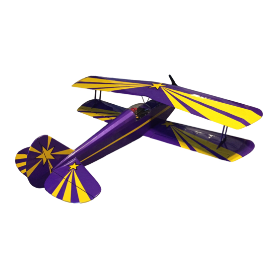
Sportster Bipe 40
Engine size
Wingspan
Wing Area
Length
Weight
Materials Needed to Complete the Sportster:
Channel radio
4
Engine
Fiberglass cloth/resin
Engine mounting bolts
Pushrods/clevises
The Sportster Bipe 40 was designed for sport flying. This biplane design with symmetrical wings pro-
vides full aerobatic maneuverability, yet has enough wing area for docile low speed capability.
The parts are machine cut and sanded for accurate fit. Should you notice a difference in size between
plans and parts, it is usually because paper changes size with moisture.
Different types of glue may be used such as epoxy, cyanoacrylate(instant glue) and aliphatic resin (white
glue). Build on a flat surface for straight wings and fuselage.
Please read through this step-by-step instruction manual before you start building so you will have an
overall idea of the construction steps and to avoid mistakes. Use the plan and parts list to identify the var-
ious parts.
This R/C kit and the model you will build is not a toy! It is capable of serious
bodily harm and property damage. IT IS YOUR RESPONSIBILITY AND YOURS
-
ALONE
to build this kit correctly, properly install all R/C components and flying
gear (engine, tank, pushrods, etc.) and to test the model and fly it only with experi-
enced, competent help in accordance with all safety standards and common
sense as set down in the Academy of Model Aeronautics Safety Code. It is sug-
gested that you join the AMA and become properly insured before you attempt to
fly this model. IF YOU ARE JUST STARTING R/C MODELING, CONSULT YOUR
LOCAL HOBBY SHOP OR WRITE TO THE ACADEMY OF MODEL AERONAUTICS
TO FIND AN EXPERIENCED INSTRUCTOR IN YOUR AREA.
Academy of Model Aeronautics
1810 Samuel Morse Dr.
Reston, VA 22090
Instruction Manual
.35-.45
45 1/2"
716 sq . in.
41 1/2"
5 - 6 1 / 2 Ibs.
Propeller
Fuel tank
Wheel collars
Spinner
Wheels
Covering
Hinges
Instant glue
Wing bolts
EPOXY
WAR N I N G !
P O BOX
788
URBANA lLLlNOlS61801
2171367
2069
Advertisement

Related Manuals for GREAT PLANES Sportster Bipe 40


Summary of Contents for GREAT PLANES Sportster Bipe 40
-
Page 1: Instruction Manual
Wing bolts EPOXY The Sportster Bipe 40 was designed for sport flying. This biplane design with symmetrical wings pro- vides full aerobatic maneuverability, yet has enough wing area for docile low speed capability. The parts are machine cut and sanded for accurate fit. Should you notice a difference in size between plans and parts, it is usually because paper changes size with moisture. - Page 2 BUILDING THE TAIL SECTION PREPARE THE FIN AND RUDDER Sandthe forward and rear sectionsof the fin if neces- sary for a good fit. Working over the plans, glue the fin section pieces together. Sand both sides of the rudder. CUT THE HINGE SLOTS IN THE FIN AND RUD- DER;...
- Page 3 GROOVE OUT THE ELEVATORS FOR JOINER WIRE CLEARANCE Cut a groove in the elevator leading edge inside of the hole so when the joiner wire is installed it will be flush with the leading edge of the elevator. Do both elevator halves. TRIAL FIT THE JOINER WIRE Temporarily install the elevator joiner wire into the elevator halves.
- Page 4 PREPARE THE RIBS Draw a rib alignment line down the center of each top wing rib. Note that the three center ribs have 2 extra notches for the cabane mounting plate. Draw rib alignment centerlines down the back of the leading edge and the front of the trailing edge.
- Page 5 ADD THE SHEETING AND CAP STRIPS Cut the sheeting to fit first then glue in place. Glue on the 1/16 x 2-1/8 x 24 leading edge sheeting, the 1/16 x 7/8 x 24 trailing edge sheeting and the 1/16 x 3 x 15 center section sheeting.
- Page 6 BUILDING THE BOTTOM WING PREPARE WING RIBS Mark all bottomwing ribs with a rib alignment center- line. Also draw centerlines down the 1/4 1/2 x 24 leading edge and the 1/4 x 1/2 x 24 trailing edge pieces. There is no top or bottom to the bottom wing at this point.
- Page 7 ADDTHE SHEETINGAND FILLER ONTHEOTHER SIDE OF THE WING PANEL When the glue is dry, turn the wing panel over, realign it to the board and glue in the balsa filler on the other side of the hold down. Sand it to shape. Add the leading edge sheeting, the trailing edge sheeting and the center section sheeting.
- Page 8 JOINING THE BOTTOM WING PANELS GLUE THE CENTER RIB TO THE LEFT WING PANEL With the wing panels "up", glue the wedge-shaped balsa center rib to the root end of the left wing panel. Make sure the wider edge of the center rib is down and that the leading edge and trailing edge are centered on the tapered rib.
-
Page 9: Building The Fuselage
PREPARE THE AILERONS Cut the aileron stock 17-1/2 tapered stock) to (5/8 x length and draw a centerline down the leading edge of the ailerons. Mark and drill the torque rod holes. Groove the aileron for torque rod clearance. Make right and left ailerons. CUTTHE HINGE SLOTS;... - Page 10 3. D GLUE THE DOUBLERS TO THE FUSELAGE SIDES Using Bulkhead #1 as a spacer, install the 1/8" balsa doublers crossgrain on the inside of the fuselage sides. Cut the doubler pieces from 1/8 x 3 x 36 balsa first, position and then glue in place.
- Page 11 FIT THE WING TO THE FUSELAGE Pin the fuselage sides together perfectly lined up. Check the fit to the wing saddle cutout by placingthe fuse sides on the wing. Custom sand if necessary but do not change the wing incidence. SAND FUSELAGE TAIL;...
- Page 12 GLUE IN BULKHEAD Realign the fuselage upside down over the plans and glue the fuse sides to bulkhead # 1 . Make sure the top of the bulkhead is flat on the building board and that the front of the bulkhead is facing forward. ADD 1/4"...
- Page 13 GLUE THE FUSELAGE TO THE DECK BASE Glue the fuselagesides/bulkhead assembly to the deck base former assembly. Fuselage sides are glued to the sides of the deck base and the sides of the formers. The deck base glues to the rear of bulkhead #3. DO NOT GLUE THE FUSELAGE SIDES TOGETHER ATTHE TAIL UNTIL THE NEXT STEP! GLUE THE HINGE/FUSELAGE TAIL;GLUE...
- Page 14 ADD THE LANDING GEAR BRACES Glue in the grooved 1/2 x 1-5/16 3-1/2 landing gear block at the bottom of bulkhead #2. Add the 1/2 triangle stock along the front of bulkhead #2 and the top of the landing gear block.
- Page 15 ADD FORMERS 1A AND 2A Glue formers 1A and 2A to the tops of bulkheads 1 and 2. When the glue is dry sand the tops of these formers to a slight angle so the top block will mate squarely when glued. Trial fit the assembled fuel tank.
- Page 16 PREPARE SMALL CABANE BLOCKS Clearance holes will have to be cut in the small cabane blocks for cabane wire clearance. Place the blocks on the cabane wire ends. The blocks should line up with the top of the fuselage. Clamp the blocks to the fuselage.Do not glue blocks yet! ALIGN THE TOP WING TO THE FUSELAGE Align the Fuselage Reference Line (top side of the...
- Page 17 SAND THE TOPS OF THE HOOD SIDE PIECES Sand the tops of the hood side pieces flush with the top of the formers so the hood top will mate squarely. GLUE ON THE HOOD TOP; SAND HOOD SIDES AT COCKPIT Trim the hood top at the cabanes first before you glue it on as it is a little difficult to sand in that area after the hood top is glued on.
- Page 18 ADD FORMERS 4A AND 5A Locatethe positions of formers 4A and 5A by placing a straight edge alongthe top stringer. Placeand gluethe formers so they mate with the top stringer and and are centered from side to side. ADD THE TURTLE DECK STRINGERS Use the 1/8 x 1/4 x 16 balsa stock and cut stringers to fit.
- Page 19 ADD NOSE FILLER BLOCK AND SPINNER RING Using your engine as a guide, locate the placement of the 2-1/4 x 2-1/4 x 1/2 nose filler block. The engine thrust washer should extend 1/16 to 1/8 inches forward of the filler block.
- Page 20 PREPARE THE FIN FILLER BLOCKS; GLUE ON THE STAB, FIN AND FIN FILLER BLOCK Prepare the fin filler blocks by cutting them to pick up the angle of the top stringer. Then sand them to the contour of the stringers. Shaping and sanding is easy if you tack glue scraps of balsa the thickness of the stab and fin to the fuselage.
- Page 21 DRILL AND TAP WING BOLT HOLES IN THE WING AND FUSE Withe fuse aligned to the work surface and the wing aligned to the fuse, drill two 11/64 pilot holes through the wing hold down plates in the leading edge of the wing and one hold in the trailing edge of the wing.
- Page 22 INSTALL RADIO COMPONENTS Glue servo rails made from scrap plywood or hardwood into the radio compartment. Install the rudder, elevator and throttle servo directly to the hardwoodrails or install the servo tray that comes with your radio. Position the battery and receiver (wrapped in foam rubber for protection) as shown on the plan.
- Page 23 TAPE INSTALL ALL CONTROL SURFACES AND CONTROL HORNS Flex the hinges back and forth a few times and then glue the hinges into the rudder and fin slots; at the ’ -AXLE HO L same time glue the tiller arm of the tail wheel into the Figure 1 rudder leading edge.
- Page 24 EXTEND THE RADIO ANTENNA RANGE CHECK YOUR RADIO SYSTEM; CHECK THE CENTER OF GRAVITY; RE- Run the antenna out of the radio compartment CHECK ALL ALIGNMENTS of the fuselage and attach it to the front of the fin. DO NOT cut the antenna wire! Your model should balance at the point shown on the plan.
- Page 25 MOUNT...
- Page 26 HAYES AL-60...
- Page 27 PREPARE THE FIREWALL Mark the top of the firewall. Mark the centerline of the engine on the firewall and center the mount in position. The thrust line of the engine should be in the same position as shown on your plan. Drill holes and install blind nuts.
- Page 28 Let’s do an example to show this. Refer to the drawing showing the OS FS-61 in the Bipe. We are going to use a Goldberg Spinner. Our “B” measurement is 5-1/8 (measure from the front of the thrust washer to the rear of the mount.
- Page 29 MWNT WIDTH EXCEEDS T H E SPACE AVAILABLE Figure 5 GENERAL INFORMATION Center of gravity:A nose heavy airplane can be a problem! Make sure you check the CG location during construction with the radio components installed. You may need to put the radio as far back in the compartment as possible.
- Page 30 SPORTSTER BlPE 40 PARTS LIST PARTNUMBER QTY DESCRIPTION PARTNUMBER QTY DESCRIPTION SS4OF22 Balsa 1/8 Former4A BALO19 BalsaTriangle1/4x36 SS4OF23 Balsa 1/8 Former 5A Balsa 1/8x1/4x36 BAL047 SS4OF24 Balsa 1/4 Former 6A Balsa1/16x3x30 BAL053 SS4OF25 Balsa 118Former 38 Balsa 1/8x3x36 BAL072 SS4OF26 Balsa 1/8 Former6B Balsa 1/16 x 3/16 x 36 BAL073...
- Page 31 Use trim MonoKote and these letters to create your trim scheme on your Sportster.
- Page 32 GREAT PLANES PRODUCT IMPROVEMENT SHEET INSTRUCTIONS FOR BALANCING YOUR SUPER SPORTSTER The best way to balance your Super Sportster is to make a The recommended balance point for the Super Sportsters is Balancing Stand from a square of 1 plywood and two 3/8" dowels.
Need help?
Do you have a question about the Sportster Bipe 40 and is the answer not in the manual?
Questions and answers