
Related Manuals for iWeld MIG 200 IGBT


Summary of Contents for iWeld MIG 200 IGBT
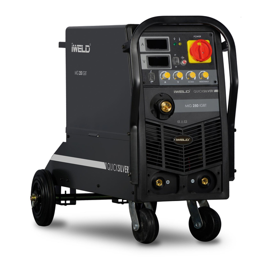
- Page 1 CUTTING EDGE WELDING USER’S MANUAL MIG/MMA Dual Function IGBT Inverter Technology Compact Welding Power Source MIG 200 IGBT MIG 250 IGBT MIG 250 IGBT Single Phase MIG 315 IGBT...
-
Page 2: Fire Hazard
WARNING! Welding and cutting is dangerous to the operator, people in or near the working area, and the surrounding, if the equipment is not correctly operated. Therefore, the perfor- mance of welding/cutting must only be under the strict and comprehensive obser- vance of all relevant safety regulations. -
Page 3: Operation
AN INTRODUCTION TO DC WELDERS INSTALLATION OPERATION CAUTIONS MAINTENANCE BREAKDOWN-CHECKING CIRCUIT DIAGRAM... - Page 4 Introduction First of all, thank you for using our welders! Our welders are made with advanced inverter technology. The inverter power sup- ply is to first rectifier the working frequency to 50/60HZ DC, and then inverter it to high frequency with high power factor IGBT (as high as 15KHZ), and rectifier again, and then use PWM to output DC power of high power factor, thus greatly reducing the weight and volume of the mains transformer and the efficiency is raised by 30%.The arc-leading system employs the principle of HF vibration.
- Page 5 The main parameter MIG 200 IGBT MIG 250 IGBTS MIG 250 IGBT MIG 315I GBT Input Power Voltage, Freq. 220±10%V, 50/60Hz 220±10%V, 50/60Hz 3x400±10%V 50/60Hz 3x400±10%V 50/60Hz (V, Hz) Rated Input Power MMA: 6,1 MIG: 6,6 MMA: 8,0, MIG: 9,2...
-
Page 6: Installation
Installation 2-1. Connection of the power wires 1. Each machine is equipped with primary powerwire, according tothe input voltage, please connect the primary wire to the suitable voltage class. 2. The primary wire should be connected to the corresponding socket to avoid oxidization. 3. - Page 7 Connect the wire feeder 1. The long axis of the wire feeder lock the wire roller that specific wire. Make sure that the wire roller is suitable for the wire used! 2. Wire should roll down clock wise, then cut the line, off-stage, it is only after pinning it 3.
- Page 8 Operation Instructions 3-1. Operation Steps 1. Open the gas cylinder valve and adjust the flow meter to the desired position. 2. Welding Torch Nozzle sizes, choose the diameter of the wire under. 3. Set the current and voltage values of the workpiece thickness and material prop- erly.
- Page 9 3-3. Choose a welding speed 1. Select welding speed affects the quality and productivity of welding. 2. When increasing welding speed, weakening the effectiveness of the shielding gas and the temperature falls, so the weld is not optimal training. If the speed is too low, the workpiece may be damaged suture training is not ideal.
-
Page 10: Maintenance
4-2 . Safety requirements Welding provides protection against overvoltage / overcurrent / overheating. If any of the above events occurs, the machine stops automatically. However, over- stress damage to the machine , keep the following guidelines : 1. Ventilation . When welding a strong current going through the machine , so the machine is not enough natural ventilation for cooling .
Need help?
Do you have a question about the MIG 200 IGBT and is the answer not in the manual?
Questions and answers