Advertisement
Table of Contents
- 1 Introduction
- 2 The Main Parameter
- 3 Installation
- 4 Operation Instruction
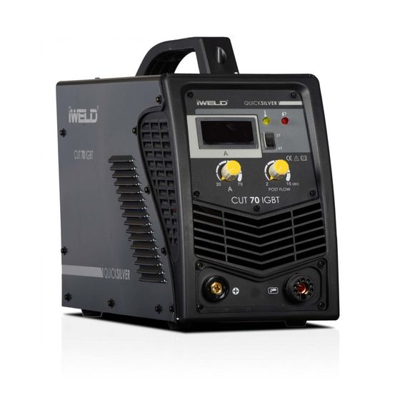
- 5 Front Panel
- 6 Working Parameters of Cutter
- 7 Air Plasma Cutting Specs for Low-Carbon Steel
- 8 Air Plasma Cutting Specs for Stainless Steel
- 9 Air Plasma Cutting Specs for Aluminum and Aluminum Alloy
- 10 Notices to Cutting
- 11 Precautions
- 12 Workspace
- 13 Safety Requirements
- 14 Maintenance
- Download this manual
Advertisement
Table of Contents

Related Manuals for iWeld CUT 50 IGBT


Summary of Contents for iWeld CUT 50 IGBT
- Page 1 CUTTING EDGE WELDING USER’S MANUAL IGBT inverter technology plasma cutting power sources CUT 50 IGBT CUT 70 IGBT...
- Page 2 WARNING! Welding and cutting is dangerous to the operator, people in or near the working area, and the surrounding, if the equipment is not correctly operated. Therefore, the perfor- mance of welding/cutting must only be under the strict and comprehensive obser- vance of all relevant safety regulations.
- Page 3 AN INTRODUCTION TO DC WELDERS MAIN PARAMETERS INSTALLATION 17-18. OPERATION CAUTIONS MAINTENANCE...
- Page 4 Introduction First of all, thank you for choosing our cutting equipment and uses. Cutting using advanced technology and a high-frequency inverter , high power IGBT rectified current, and then by using the PWM output direct current makes it suitable for high-performance work , greatly reducing the weight and dimensions of the main transformer 30% increase in efficiency.
- Page 5 The main parameter Parameters\Model CUT 50 CUT 70 800CUT50IGBT 800CUT70IGBT Input power voltage (V) AC 220V +- 15% 50/60Hz AC 380V +- 10% 50/60Hz Rated input current(A) 28,5 14,5 No-load voltage (V) Output current scope (A) 10-50 20-70 Rated output voltage (V) Load duration rate (%) Efficiency (%) Power factor(Cosφ)
- Page 6 Installation Distribution box connected to 220V Pressure reducing valve IN Air duct Ground Workpiece Earth clamp Connected to the cutting gun Ground The connection diagram of the cutter is shown above. Be sure to use this welding machine with the specified cutting gun, earth clamp together;...
-
Page 7: Operation Instruction
Operation Instruction Front Panel ③ ③ ④ CUT70C IGBT ① POWER ④ ① POWER ⑤ ⑦ ② ⑥ CURRENT ② ⑥ POST GAS POST GA PILOT ARC Digital panel meter AC 220V Current adjusting knob Abnormity indicator Power indicator Power switch Post-blow adjusting knob 2T/4T switch Power incoming wire... - Page 8 - 2T/4T button: “2T” n is short welding, pressing button will power up when released, stop power supply. The first is the power button is pressed “4T” was and will remain so until the next time you press the button. - Given current : The cutting power within the specified range of the parameter table, the corresponding value for the work must be adjusted.
- Page 9 3-3. Notices to Cutting • When preparing for cutting, hold the cutting gun (the cutting gun does not contact the workpiece for a model of non-contact arc striking) and press the gun switch; at this time, plasma arc will eject from the nozzle hole, indicating the electrode, nozzle, etc are installed correctly.
- Page 10 4-2 . Safety requirements Welding provides protection against overvoltage / overcurrent / overheating. If any of the above events occurs, the machine stops automatically. However, over- stress damage to the machine , keep the following guidelines : 1. Ventilation . When welding a strong current going through the machine , so the machine is not enough natural ventilation for cooling .
Need help?
Do you have a question about the CUT 50 IGBT and is the answer not in the manual?
Questions and answers