
Related Manuals for Sony AWS-750


Summary of Contents for Sony AWS-750
-
Page 1: Operating Instructions
4-463-319-13 (1) Live Content Producer Operating Instructions Before operating the unit, please read this manual thoroughly and retain it for future reference. AWS-750 Software Version 1.2 © 2013 Sony Corporation... -
Page 2: Table Of Contents
Step 4: Video Switching ......28 Table of Contents Switching after Viewing a Preview Video ..........28 Switching the PGM Directly Important Notes..........5 (Direct Take) ........29 Copyrights ........... 5 Using Transition Effects ......30 Note on Faulty Pixels on the LCD Panel ..5 Step 5: Audio Mixing ....... - Page 3 Lighting Tallies on Cameras Connected via Recording Outputs from the Unit to the GPI ..........52 Internal Storage......... 76 Playing Back Material Files in the Media Configuring Recording Settings ....76 Player..........53 Starting and Stopping Recording ..... 77 Entering Text ..........54 Streaming ..........
- Page 4 [Video Setup] Screen ........ 97 NOTICE TO USERS [Audio Setup] Screen ........ 99 © 2013 Sony Corporation. All rights reserved. This [Others] Screen ........100 manual or the software described herein, in whole or in [Service Log] Screen ......101...
-
Page 5: Important Notes
Internet or otherwise may in some • Sony will not be liable for any data that fails to be cases require the permission of the copyright holder of the recorded onto the internal storage during use of the video or audio. -
Page 6: Version Update History
The following functions have been added to V1.2 of templates. AWS-750. For details, see “Creating Titles (Titler)” (page 82). Tracking function You can now automatically track a specified object (e.g.,... - Page 7 Note This function is only supported on AWS-750 units that support HDCP (i.e., units with the following serial numbers). Serial number: 11001 or later Timecode output function Timecodes are now embedded in HD SDI outputs. Version Update History...
-
Page 8: Overview
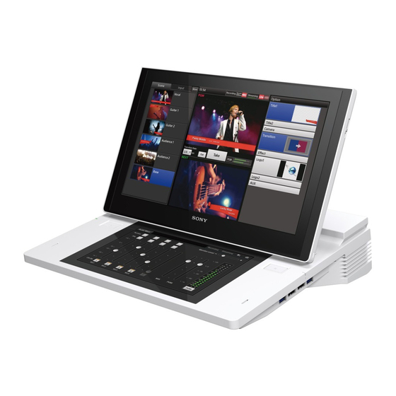
Background video Overview Logo 1 Title 1 Features The AWS-750 Live Content Producer is an all-in-one audiovisual production system equipped with video switching, camera control, audio mixing, and live Internet distribution functions. Video switching and audio mixing Logo 2 Title 2 can be performed via simple operations. -
Page 9: Audio Mixing
Recording to internal storage You can record video composites and mixed down audio to the unit’s internal storage. The recorded files can be edited using various nonlinear editors. Two-channel output (AUX) In addition to PGM, another video output (AUX) is available on this unit. -
Page 10: System Configuration And Operation Flow
Camera Microphone Camera Computer used for presentation PA system/Speaker AWS-750 Preparation settings • Video input/output settings (page 97) Inserting titles and logos (page 44) • Audio input/output settings (page 99) • Creating titles (page 44, 82) • Preparing logos (page 44, 88) Mixing audio (page 31) •... -
Page 11: Use In Lectures And Seminars
Blu-ray disc / Computer used for displaying materials Nonlinear editing device AWS-750 Preparation settings Controlling remote cameras (page 47) • Recording settings (page 76) • Remote camera settings (page 93) Mixing audio (page 31) • Camera angle settings (page 47) -
Page 12: Parts Identification
Parts Identification Front The unit’s displays are touchscreens. For details on When headphones are connected to the operations, see “Using the Touchscreens” (page 21). HEADPHONES jack, output from the internal speakers is disabled. a Main display e Sub display Displays the main screen used for performing video switching operations. -
Page 13: Left
Left a Ventilation holes Do not block the ventilation holes. Doing so may cause internal overheating, resulting in fire or damage to the unit. When moving the unit after use, allow the unit to cool down sufficiently beforehand. b 1 (power) switch Turns the unit on or off (page 25). -
Page 14: Right
Right a USB ports ×4 For details, see “Opening and Closing the Main Display” (page 18). Connect USB storage devices, keyboards, and other external devices here. d LAN 1 connector (RJ-45 modular jack) The SuperSpeed USB (USB3.0) is supported. USB cameras and other USB devices not mentioned Connect this to a network when you want to perform in this document are not supported. -
Page 15: Rear
Rear Cable clamp 1 AUDIO INPUT 4 VIDEO OUTPUT 3 VIDEO INPUT block block block Cable clamp Cable clamp 2 AUDIO OUTPUT block a DC IN 19.5V (DC power input) connector Attach the hooks of the panel cover here (page 18). Connect the supplied AC adapter here. -
Page 16: Audio Output Block
Inputs analog video signals. HD/SD SDI (SDI input) connector 3 (BNC type) Notes Inputs HD/SD-SDI signals. • Use a Sony HDMI cable. Recommended cable example: HIGH SPEED HDMI CABLE DLC-HJ20 (2 m (6.6 feet)) COMPOSITE connector 3 and HD/SD SDI •... -
Page 17: Video Output Block
• Audio PGM: PGM audio AUX: MIX audio For details on selecting PGM or AUX, see “[Video Setup] Screen” (page 97). Note Use a Sony HDMI cable. Recommended cable example: HIGH SPEED HDMI CABLE DLC-HJ20 (2 m (6.6 feet)) Parts Identification... -
Page 18: Opening And Closing The Main Display
Lift the areas near the release levers, and slide the Opening and Closing the main display in the direction of the arrow. Main Display Opening the Main Display Lift the front portion of the panel cover to unlock it. The magnet locks will lock the display into place. Open the panel cover. -
Page 19: Closing The Main Display
Closing the Main Display Applying the Anti-Glare Films Hold the sides of the main display as illustrated, and pull the display in the direction of the arrow. The magnet locks will release. Anti-glare films are supplied with this unit to protect the touchscreen displays. - Page 20 Placement Wipe in a single direction from right to left. Center the film so that the surrounding uncovered Verify that all specks of dust have been removed from edges of the display are even. the surface of the main display. Anti-glare film Place the anti-glare film back on the main display.
-
Page 21: Using The Touchscreens
Verify that there are no air bubbles or leftover dust, Using the Touchscreens and remove the vinyl tape. Use the screen-cleaning solution and cleaning cloth to wipe the anti-glare film. You can perform touchscreen gestures on the main display and sub display with your fingers in place of Applying the film to the sub display keyboard and mouse operations. -
Page 22: Tap And Hold
Tap and hold Hold your finger in place for at least 1 second after tapping. Use this gesture to perform operations, such as displaying context menus and viewing filenames that end in “…” in their entirety. Drag Slide your finger while holding it on the screen. This performs the same operation as dragging on a mouse. -
Page 23: Getting Started
• Channel fader assignments Getting Started Name Signal name Input (L) Input (R) Fader 1 MIC1 MIC/LINE1 MIC/LINE1 Fader 2 MIC2 MIC/LINE2 MIC/LINE2 Operation Flow Fader 3 MIC3 MIC/LINE3 MIC/LINE3 Fader 4 MIC4 MIC/LINE4 MIC/LINE4 Fader 5 Used for audio embedded in SDI or HDMI signals or in videos played back in the Media This chapter describes the procedures for using the unit Player (i.e., embedded audio). -
Page 24: Step 1: Connecting Devices
Step 1: Connecting Devices Connect the various devices to the rear of the unit. If you have already connected the devices, proceed to “Step 2: Turning the Unit On” (page 25). Connection example Remote camera (page 93) Projector Computer Condenser microphones Camera with HD SDI output Headphones AC adapter... -
Page 25: Step 2: Turning The Unit On
Note Step 2: Turning the Unit This unit is designed to be used with the main display in its upright position. Do not perform operations with the main display closed. Turning the unit on Turning the unit off Press the 1 switch on the left side of the unit. Connect the DC output plug of the supplied AC A confirmation message appears. -
Page 26: Step 3: Initial Settings
Tap [System] in the menu to the left. Step 3: Initial Settings Specify the video signal format that will be handled by the unit and the date and time. If necessary, you can also adjust the brightness of the display. If you have already configured these settings, proceed to “Step 4: Video Switching”... -
Page 27: Adjusting The Display Brightness
Tap the tab to display the [System Setup] screen, drag the values up or down, or tap [+] or [–] to and then tap [Date/Time]. display the values. A confirmation message appears. 3 Tap [Shutdown]. The unit shuts down. The [Date/Time] screen appears. 4 Press the 1 switch on the left side of the unit to Select the time zone. -
Page 28: Step 4: Video Switching
Tap [Take]. Step 4: Video Switching [Take] This section describes how to select an input source in the [Input] list and switch the program output video via simple operation. Video switching is performed in the main screen. Switching after Viewing a Preview Video The video in the [NEXT] viewer appears in the You can switch to the next video that you want to use for... -
Page 29: Switching The Pgm Directly (Direct Take)
Videos switch from one to the next. Tap anywhere inside the [PGM] viewer to enter direct mode. Tap inside. Direct mode is enabled, and the [NEXT] viewer display dims. In direct mode, “Direct Mode” appears in the [NEXT] viewer. Under default conditions, tapping [Take] dissolves Dims during direct mode. -
Page 30: Using Transition Effects
In the [Option] menu, tap the area on the right side of the [Transition] button. Direct mode can also be used for switching operations Tap this area. outside of the [Input] list. Using Transition Effects You can select from the following transitions for video switching on this unit. -
Page 31: Step 5: Audio Mixing
The default transition rate is 1.0 second. Step 5: Audio Mixing You can mix the audio being input to the unit and mix it down to stereo program audio. Audio operations are performed in the sub screen. This section describes how to adjust the audio for each microphone and mix multiple audio channels. - Page 32 For details on configuration, see “[Input Channel In addition, the audio level meter switches to PFL mode Assign]” (page 99). (the button display switches to [PFL]) while the [PFL] button is held down, allowing you to check the levels of Viewing the audio level meter the audio input.
-
Page 33: Basic Operations
Video switching is performed in the main screen, while Basic Operations various adjustments and settings are performed in the sub screen. The results of adjustments and settings are applied immediately in the main screen. Depending on the adjustments and settings, perform them while viewing the Using the Screens main screen. -
Page 34: Recording Status
[Input] list: Displays a list of videos being input to remaining time is continuously updated based on the unit’s input connectors, signals created the status of the internal storage. internally on the unit (i.e., black and color bar [REC]: When recording is in progress, this lights red. signals), and other input sources. - Page 35 [Logo 1] / [Logo 2]: Insert logos onto video • When the button is closed (page 44). Tapping any area will display the list. [AUX]: Select the material to output to AUX after a take (page 70). To enable or disable options (protect) icon Tap the following area of the button to enable or Indicates that the current title or logo is protected.
-
Page 36: Option List
i Option list When you lock the status, the icon appears in the [Option] menu and [AUX] list of the main screen. Displays a list of content for the option. Select the content you want to add to videos in this list. •... -
Page 37: Sub Screen
mark For details, see “ Icon Displays in Lists” (page 103). This warning mark appears if a problem exists with materials in the [Scene] list or [Option] menu. Sub Screen You can perform adjustments, configure settings, and enter text in the sub screen. Tapping each tab displays its respective operation screen. - Page 38 For details, see “Compositing Videos Using Picture- in-Picture (PinP)” (page 56) and “Inserting People onto Backgrounds (Chroma Keying)” (page 60). [Logo] tab Appears when the [Logo 1] or [Logo 2] list is displayed in the main screen. Allows you to adjust the logo position. For details, see “To adjust the position”...
-
Page 39: Input Sources
Creating Lists You can create lists by adding materials to the [Input] list, [Title 1]/[Title 2] list, [Logo 1]/[Logo 2] list, and [AUX] list. Lists are created using the context menu that appears when you tap and hold an area within the respective list. The operations that can be performed and the materials that can be added will differ depending on the list. -
Page 40: Adding Input Sources To The Lists (Add Source)
Tap [Close] to close the dialog box. Adding Input Sources to the Lists The input source is added to the specified position. (Add Source) Add the external signals configured in the [Video Setup] screen of the [System Setup] menu and the unit’s internally generated signals to the lists. -
Page 41: Adding The Media Player To The Lists (Add Media Player)
Tap the file you want to add to place a check mark on it, and then tap [OK]. Only one instance of the Media Player can be added per You can select multiple files. list. Display the context menu in the position you want to add the Media Player, and select [Add Media Player]. -
Page 42: Editing Text Created In The Titler (Edit)
If you perform the operation on a button, the item will Editing Text Created in the Titler be added below that button. (Edit) You can start the Titler directly from a list and edit text for still images that were created using the Titler. Display the context menu on the button of the still image you want to edit, and select [Edit]. -
Page 43: Removing Material Buttons From The Lists (Delete)
Drag the move handle of the button you want to move Removing Material Buttons from the to the desired position. Lists (Delete) Dragging an area other than the move handle will not move the button. Display the context menu on the button of the material you want to delete, and select [Delete]. -
Page 44: Inserting Titles
Inserting Titles To produce a desired image, clip, gain, and density adjustments are required. You can insert titles onto the program video using one of For details on the clip, gain, and density settings, see the following three methods. “To adjust the appearance of composites” (page 45). •... - Page 45 When you select a title in the [Title 1] list, the title appears in the [NEXT] viewer. The [Title 1] list closes, and the [Option] menu Select the title you want to insert. appears again. The thumbnail of the selected title appears on the [Title 1] button.
-
Page 46: Inserting Logos
Select the logo you want to insert, and adjust its Inserting Logos position. When you select a logo in the [Logo 1] list, the logo appears in the [NEXT] viewer. You can insert up to two still images at 320 × 320 size as Select the logo you want to insert. -
Page 47: Controlling Remote Cameras
Enabled Controlling Remote Cameras You can perform the following controls for cameras connected to the unit via VISCA cable. • Controlling and adjusting cameras (page 47) • Saving adjustments as presets (page 49) • Recalling presets (page 50) • Lighting tallies on remote cameras (page 51) To control a camera, you must assign the VISCA camera as an input source in the [Input] list and perform Displayed... - Page 48 Perform pan/tilt, zoom, iris, and other operations • Although pan/tilt operations and zoom operations while viewing the video in the [NEXT] viewer. can be performed simultaneously in the sub screen, the [Pan/Tilt] adjustment handle and the [Zoom] slider cannot be operated simultaneously in the Pan/tilt (page 48) main screen.
-
Page 49: Saving Adjustments As Presets
[White Balance]: Select one of the following white balance modes. This setting can only be configured when [Iris] is set to • [Auto]: Automatic adjustment. auto mode. Backlight compensation is disabled when • [Indoor]: Indoor mode. [Iris] is set to manual mode. •... -
Page 50: Recalling Presets
Select [Camera] in the [Option] menu. Renaming presets Display the context menu of the preset you want to rename, and select [Rename]. When the virtual keyboard appears, you can enter up to 20 alphanumeric characters. Deleting presets from the list Display the context menu of the preset you want to delete, and select [Delete]. -
Page 51: Lighting Tallies On Remote Cameras
Lighting Tallies on Remote Using the GUI Tally Cameras Function The tally on a remote camera will light while its video is being used for PGM output. (This does not require any configurations.) You can display tallies on the source buttons in the [Input] list that light for the sources being used as the PGM output and NEXT selection sources. -
Page 52: Using The Camera Tally Function
Connect the camera to the unit. Using the Camera Tally Connect the GPI connector on the unit to the TALLY Function connector on the CCU. For details on pin assignments on the GPI connector, see “GPI connector” (page 113) in the “Connector You can have the tallies on cameras light via the VISCA Pin Assignments”... -
Page 53: Playing Back Material Files In The Media Player
Select the category to which the file belongs, select Playing Back Material the file to play back, and then tap [OK]. Files in the Media Player Categories The following material files can be played back in the Media Player. • Movies and still images imported to the unit’s internal storage •... -
Page 54: Entering Text
Tips Entering Text • Embedded audio will be assigned to channel fader 5 automatically. • When the [Media Player] tab is displayed, the unit Text is entered in the sub screen using the virtual enters audio preview mode automatically, allowing keyboard. -
Page 55: Using The Virtual Keyboard
Using the Virtual Keyboard The following image of the virtual keyboard is a sample. Depending on the functions you are using, the keyboard that is displayed may differ. The keyboard that is displayed will differ depending on the input language. For details on changing the input language, see “[Input Language]”... -
Page 56: Advanced Operations
Pattern_09 Pattern_10 Advanced Operations Compositing Videos Using Picture-in-Picture Pattern_11 (PinP) You can composite a video consisting of one video (overlay video) inserted on top of another video (background video) using the picture-in-picture effect. You can use up to two overlay videos. Selecting Composite Patterns Inserted image (overlay video) -
Page 57: Selecting Composite Materials
Canceling composites Selecting Composite Materials Use one of the following methods. Select the videos you want to use for the composite in the • Select [Off] in the [Effect] list [Input] list. Select [Off]. In the [Option] menu, tap the input control number button on the [Effect] button. -
Page 58: Adjusting Overlay Videos
Configuring the [Density] settings Adjusting Overlay Videos Specify the opacity of the inserted image. In the [Option] menu, tap the input control number button on the [Effect] button. Display the [Effect] list. In the sub screen, tap the [Effect] tab to display the [Effect] screen, and select the settings you want to adjust in the menu to the left. - Page 59 Configuring the [Transformation] settings Item Setting values Adjust the size and position of the overlay video. Left Bottom Right [Full] –100 +100 –100 +100 [4:3] –75 +100 –100 If you move the adjustment handles after enabling [Full] or [4:3] (highlighted in blue), the button will turn off (no longer highlighted), indicating deviation from the [Reset] settings.
-
Page 60: Inserting People Onto Backgrounds (Chroma Keying)
Composite example: Inserting People onto Overlay video 1 (for chroma keying) Background video Overlay video 2 Backgrounds (Chroma Keying) You can use chroma keying to insert a person onto a Composite with PinP added background, for example. Overlay video 2 Chroma keying is a compositing technique that involves specifying regions of a single color in the overlay video (green in the following example), and inserting the... -
Page 61: Selecting Composite Materials
The video composite appears in the [NEXT] viewer according to the selected effect pattern. If you want to use still images for the overlay image, use the Media Player. For details on adding the Media Player, see “Adding the Media Player to the Lists (Add Media Player)” (page 41). - Page 62 • [Transformation]: Adjust the size and position of [Color Cancel]: Use this if remnants of the color that overlay video 1 (page 63). is supposed to be removed appear in the outlines of the inserted image (e.g., in a person’s hair). When [On] is selected, the remnants of the Adjusting [Chromakey] in [Auto] mode specified color in the outlines are made colorless...
-
Page 63: Adjusting Overlay Video 2
• [On]: Do not composite. Adjusting Overlay Video 2 Titles and logos are not composited, making it easier to perform manual adjustments. In the [Option] menu, tap [3] (overlay video 2) on the • [Off]: Composite. [Effect] button. This is useful when you want to confirm the image’s appearance with titles and logos Display the [Effect] list. -
Page 64: Creating Scenes
Configuring the [Border] settings Creating Scenes Specify whether to add a border to the edges of overlay video 2. You can save the current state of the [Input] list, [Option] menu, and the transition rate to the [Scene] list as a “scene.”... -
Page 65: Editing Scenes
A button is added to the [Scene] list. The image that In the [Scene] list, display the context menu of the was currently displayed in the [NEXT] viewer button to which you want to save the edited scene, appears as the thumbnail. and select [Save]. -
Page 66: Recalling Scenes
Recalling Scenes Tracking Targets Video conditions that are saved to a scene can be selected (Tracking Function) as the program video. Previously saved scenes are displayed in the [Scene] list. Using the tracking function allows you to perform the For details on saving scenes, see “Creating Scenes” following controls. -
Page 67: Enabling The Tracking Function
Enabling the Tracking Function The mode cannot be changed while the camera is moving. Display the [System Setup] screen, and tap [Video]. Wait for the camera to stop before tapping [Tracking]. The tracking status appears in the [NEXT] viewer during tracking mode. - Page 68 Tap the [Camera] tab to display the [Camera] screen, By specifying the movement range, you can prevent and tap the camera from pointing in unintended directions during tracking and make sure that your target does not move out of the camera’s view. Adjustment handle The [Tracking Settings] screen appears.
- Page 69 Performing adjustments according to the tracking target If you configure the [Pan/Tilt Limit Setting] settings, Perform adjustment in the [Tracking Settings] screen. be sure to save the settings to [Preset_1]. The unit starts with the settings that are saved to [Preset_1]. If you do not save the settings to [Preset_1], the settings will revert to previous values.
-
Page 70: Using Framing Mode
Using Framing Mode Switching the Second Output (AUX) Framing mode will not function if an [Effect] is configured. In addition to PGM, another video composite output (AUX) is available on this unit. In the [Input] list, tap the input source for which the You can select the AUX output from the input sources tracking function is enabled to display its video in the and the PGM. -
Page 71: Configuring Aux Settings
Outputting AUX from the PGM/AUX output Configuring AUX Settings connectors Specify the connectors (RGB output, HDMI output, or Configuring [Clean] settings SDI output connectors) you want to use for AUX output as [AUX]. To output an AUX signal that consists of the PGM output with titles and logos removed, select [Clean] in the Display the [System Setup] screen, and tap [Video]. - Page 72 If you select [PGM], the output will be identical to the Excluding AUX outputs from scenes PGM output. If you save a scene while the AUX button is open, the If you select [Clean], the output specified in the AUX selection will also be saved. To exclude an AUX [System Setup] menu >...
-
Page 73: Performing Detailed Audio Adjustments
[Input Trim]: Adjust the audio input signal level Performing Detailed (page 74). [Pan]: Adjust the left and right balance of the audio Audio Adjustments (page 74). When you finish configuration, tap You can adjust the audio quality for each channel The [Access] screen appears again. -
Page 74: Switching The Monitored Audio
[Filter] [Input Trim] Use the filter function to cut high frequencies and low Adjust the input signal level so that the proper input level frequencies. This is useful for minimizing noise. is obtained when the fader is set to the 0 dB position. [High Cut (8kHz)]: When [On] is selected, high [Trim]: Adjust the input level within a range of –15 dB frequencies (8 kHz) are cut at 12 dB/Oct. -
Page 75: Adjusting Mix Out Output Levels
Tapping [PGM]/[MIX] in the [Audio Mixer] screen switches between PGM output and MIX output. When compositing video using PinP or chroma keying, the [Input] tab will only appear when an input source from the [Input [1]] list is selected. Embedded audio cannot be used for input sources in the [Input [2]] and [Input [3]] lists. -
Page 76: Recording Outputs From The Unit To The Internal Storage
For details on the formats of the files recorded by this fader 5. unit, see “Recording format” (page 111). For further details, contact your dealer or local Sony representative. Configuring Recording Settings Settings related to recording are configured in the [Recording] screen of the sub screen. -
Page 77: Starting And Stopping Recording
[Audio Source]: Select [PGM] or [MIX] as the audio you When recording starts, [REC] changes to [Stop], and the want to record. [REC] status displayed at the top of the main screen lights [Bit Rate]: This is fixed at 35 Mbps (HQ Mode). red. -
Page 78: Streaming
Connect a network cable to the LAN 1 connector on Streaming the right side of the unit, and connect to a network. in the sub screen to display the [System Setup] screen, and tap [Network]. Program video can be encoded on the unit and streamed live using an external server or saved to the unit’s internal storage. -
Page 79: Starting And Stopping Live Streaming Transmissions
[High Bandwidth-Flash]: Flash settings for the high bandwidth. [Medium Bandwidth-Flash]: Flash settings for the middle bandwidth. [Low Bandwidth-Flash]: Flash settings for the low bandwidth. c [Video Source] Select [PGM] or [AUX] as the video you want to encode with this unit. d [Audio Source] Select [PGM] or [MIX] as the audio you want to encode with this unit. -
Page 80: Recording Vod Files
Stopping transmission Starting recording Tap [Stop]. Tap [Start]. Recording starts. A confirmation message appears. When you tap [Yes], During recording, [Start] changes to [Stop] and the transmission stops and the [Live] streaming status and recording time appears (hh:mm:ss). In addition, the throughput indicator turn off. -
Page 81: Using External Devices For Video Switching And Other Operations
Item Description Using External Devices Go to Display the [Option] menu. When Option one of the [Option] menu’s lists is for Video Switching and Menu displayed, pressing this key returns to the [Option] menu. Other Operations Title/Logo Enables/disables [Title 1]. On/Off Enables/disables [Title 2]. -
Page 82: Creating Titles (Titler)
The Titler starts, and the [Folder] dialog box for Creating Titles (Titler) selecting the folder in which to save the file appears. The virtual keyboard that allows you to enter text appears in the sub screen. This unit includes a “Titler” function for creating title To create a new folder, tap [New Folder]. -
Page 83: Using The [Titler] Screen
Select the template you want to use, and then tap The [Titler] screen appears using the selected [Select]. template. To display a list of presets that are preinstalled on the unit, tap the [Preset] tab. To display a list of user templates, tap the [User] tab. -
Page 84: File List
a File list editing area. It will not be used as the background of the title. Displays a list of titles stored in the currently opened [Close]: Quit the Titler. folder. The folder name appears at the top left. c Editing area (page 85) Folder name Edit the title in this area. -
Page 85: Creating Titles
selected object. A caret appears, allowing you to Creating Titles enter text. Display the context menu in the file list, and select [Create New]. The [Template] dialog box appears. Caret Tap the template you want to use, and then tap [Select]. -
Page 86: Managing Files (File Manager)
Verify that the selected title has been added to the Managing Files (File user template list. The user template will be automatically named Manager) “UserTemplate_<number>.” In the [User] tab, information on the selected template is displayed here. You can manage the following types of files stored on the unit’s internal storage using the File Manager. -
Page 87: Using The [File Manager] Screen
Using the [File Manager] Screen a Categories c [Import] tab Files stored on the internal storage are divided into Allows you to import files stored on USB storage the following categories. When you select a category, devices and other external drives to the unit’s internal a list of files appears in the 5 file list. -
Page 88: File Information
g [Delete] Deletes the files for which the checkboxes are selected in the list. h [Remain] indicator Displays the remaining space on the internal storage. i File information Displays the thumbnail and resolution of the file selected in the list. The virtual keyboard closes, and the file is renamed. - Page 89 For fonts Importing files Copy the files you want to import to an external drive Extension .ttf, .pfb, .otf beforehand. For user templates used in the Titler Tap the [Import] tab to display the [Import] screen. Recommended size 1920 × 1080 Select the category of the file you want to import.
-
Page 90: Exporting Files
Select the checkboxes of the files and folders you Tap V in the list to the right, select the external drive want to import, and tap [Import]. to which to export in the list that appears, and then tap [Export]. You can select multiple files. -
Page 91: Saving And Loading Settings
Select the target external drive, and tap [OK]. Saving and Loading Settings You can save the current setting configurations to the internal storage as files (up to 99). These files are referred to as “projects.” Some conditions, such as tab selection states, are not If the external drive is portioned, each partition will saved. -
Page 92: Loading Settings
Loading Settings Select the project file you want to load in the [Load] screen of [Project], and tap [Load]. The project file is loaded onto the unit. Restoring Default Settings To reset list and [System Setup] conditions to their default conditions, tap [Default] in the [Load] screen. -
Page 93: Remote Camera Connections And Settings
Settings the address numbers to specify which cameras to control. For details configuring address numbers, refer to the instruction manual for the remote camera. Remote Camera Supported models Sony remote cameras Connections and • BRC-H700 • SRG-300H Settings • BRC-H900 •... - Page 94 • Display the [Camera] context menu in the [Option] menu, and select [Reset Camera] Cameras for which remote control is enabled appear as “address (model name).” When the reset the cameras, connection will be reestablished for all cameras connected for remote control.
-
Page 95: Configuring System Settings ([System Setup] Menu)
Displaying the [System Setup] Configuring System Screen Settings ([System Setup] Tap the tab at the top right of the sub screen to display menu) the [System Setup] menu. You can configure the following system settings in the [System Setup] menu. Screen Description Reference... - Page 96 [IPv4] [Mode]: Select the mode for the IP address and other settings. Configure the IP address and other settings for use in IPv4 • [Off]: Do not use IPv6. network environments. • [Manual]: Enter the settings manually. When this is Tap [Apply] after configuring each setting.
-
Page 97: [Video Setup] Screen
[Apply]: Apply the settings. [SD Input Aspect]: Select the aspect ratio for SD input signals. If further information is required, contact your local Sony • [4:3 (Center)]: Center the 4:3 aspect ratio (i.e., representative. fitted to the top and bottom of the display with black bars on the left and right). - Page 98 When a remote camera that is not supported by the audio, regardless of this setting. unit is connected, its model name will appear as • For details on whether your AWS-750 unit supports “Unknown.” Some functions will not be available in the [HDCP Handling] setting, see“HDCP such cases.
-
Page 99: [Audio Setup] Screen
[SD Output Aspect]: Select the aspect ratio for SD [Audio Setup] Screen output signals from the SDI PGM connector. • [Letter Box]: Output with black bars on the top and Configure audio input and output settings and adjust bottom of the display. settings. -
Page 100: [Others] Screen
[PGM OUT]: Select this checkbox when you want to [OUT Level]: Adjust the output level of the oscillator output the audio of channel faders 1 to 5 to PGM signal. OUT. Drag the slider to adjust within a range of –∞ to [MIX OUT]: Select this checkbox when you want to 0 dBFS. -
Page 101: [Service Log] Screen
For details on tallies, see “Using the GUI Tally Function” (page 51). [Transition Rate] Configure the selectable options for the transition rate in the main screen. [Rate 1] to [Rate 3]: Configure the three selectable options that will appear in the drop-down list. Tap each setting value to display a dialog box, configure the transition rate within a range of 0.0 to 4.9 seconds, and then tap [Set]. -
Page 102: Appendix
You can also access the information from the following URL. The currently installed version and the version of the http://www.sony.net/ update package are displayed. Notes Check the versions, and tap [Yes] when you are ready to install. -
Page 103: Troubleshooting
Check the status in the [Option] menu, and perform the from the lists the next time the unit is started. appropriate operation. Problems and Solutions Check the following before requesting repairs. If the problem persists, contact your local Sony representative. Symptom Possible cause Solution... - Page 104 Symptom Possible cause Solution Videos do not appear in the lists. The connected device is not turned Restart the device. The cables are not connected Connect the cables properly. properly. The video input signals are not Assign the video input signals properly. assigned properly.
- Page 105 EVI-H100S cameras. after it is enabled. I want to restore the factory default Contact your local Sony representative. conditions. Configured date and time settings Incorrect date and time displays Contact your local Sony representative.
-
Page 106: Maintenance
Main display open Maintenance Remove dust from the ventilation holes once per month or whenever necessary. Specifications Main Unit 415 mm (16 in.) General Power requirements 19.5 V DC, 9.2 A AC adapter Operating Voltage: 100-240 V AC, 2.5A, 50-60 Hz Power consumption 160 W Operating temperature... -
Page 107: Supplied Accessories
= 45 V (max.) HDMI HDMI (Type A) (2) VISCA 5 pin in-line connector (1) RS-422 equiv. VIDEO OUTPUTS Sony VISCA camera commands are HD/SD SDI BNC type (2) supported. SMPTE-292M, SMPTE-259M-C Baud Rate: 38400 bps HD SDI BNC type (1) Main display: 15.6"... -
Page 108: Performance
PinP: Single (2 patterns), Double (9 patterns) • Always verify that the unit is operating properly Chromakey: Standard, Chromakey + before use. SONY WILL NOT BE LIABLE FOR PinP DAMAGES OF ANY KIND INCLUDING, BUT Key source Title: Input Signals or Internal Still NOT LIMITED TO, COMPENSATION OR Picture (up to 1920 ×... -
Page 109: Supported Input Formats
Titler Audio HD SDI 24-bit, SD SDI 20-bit, 48 kHz, 2 ch (select from 1/2 ch or 3/4 ch), L-PCM Preinstalled fonts 17 fonts including SST Medium, DFHei-W5-A, SST Japanese Pro Regular, and YDGothic 100 Pro COMPOSITE (composite video input) Preinstalled 100 patterns and more connectors 1 and 3... -
Page 110: Supported Output Formats
Line number HDMI connector 2: Not supported HD SDI VITC Line 9 and line 571 HDMI connector 4: Supported only on AWS-750 units that support HDCP (i.e., units with the following serial Line 9 and line 571 numbers). Line 10... -
Page 111: File Formats
HDMI (output) connector Recording function Video Recorded video format Determined by the [System Setup] > [Video Setup] > Resolution Frequency / ip [System] > [System Format] setting (page 98). 640 × 480 (VGA) Recording format 1024 × 768 (XGA) Format MPEG HD (.mxf) 1280 ×... -
Page 112: Data Saved To Projects
VOD recording format Item Can be saved Location Setting Extension .f4v [PGM] viewer Video display Video codec H.264 960 × 540, 30/25 fps, 800 kbps [NEXT] viewer Video display Audio codec Selection of 48 kHz, 96 kbps adjustment handles overlaid in the [NEXT] Recording Video: PGM or AUX viewer... -
Page 113: External Keyboards
As the baud rate is fixed at 38400 bps, configure the [Project] setting on the remote camera side. [About Anycast] Connection example: [Service Log] Virtual keyboard Page selection AWS-750 Remote cameras Mode selection Control VISCA VISCA Shift Cam 1 Caps Lock... - Page 114 VISCA RS-422 connector RXD OUT – Use a 5-conductor cable RXD OUT + consisting of two twisted pairs and a grounding AWS-750 TXD OUT – wire (e.g., a Category 5 VISCA connector TXD OUT + Ethernet cable). RXD IN –...
- Page 115 VISCA RS-422 connector RXD OUT – Use a 5-conductor cable RXD OUT + consisting of two twisted pairs and a grounding AWS-750 TXD OUT – wire (e.g., a Category 5 VISCA connector TXD OUT + Ethernet cable). RXD IN –...
-
Page 116: General Limitation On Transitions
General Limitation on Transitions In the following types of composites, videos may cut to each other despite transitions being configured or composites may not be displayed during transitions. In addition, if even one of the following conditions is met, the other transitions may also be affected. Condition 1 A transition is executed within the same title. -
Page 117: Glossary
Embedded audio Logo Glossary Audio that is included in a video A permanently visible mark that is signal. shown on videos and used to indicate copyrighted material, for example. Encoding Black burst signal Data rate conversion that uses A reference signal used to achieve compression technology and is A new picture is mixed into an old external synchronization (GenLock). - Page 118 Serial digital interface (SDI) VISCA A standard for transmitting A protocol developed by Sony which uncompressed digital video signals allows video equipment to be and embedded audio over a single connected to computers. coaxial cable. VOD (Video On Demand) SNMP (Simple Network...
-
Page 119: Index
HDMI (HDMI input) connector 2 16 Index HDMI (HDMI input) connector 4 16 Date and time 26 HDMI (output) connector 17 [Date/Time] 27 HEADPHONES jack 13 DC power input connector 15 Symbols Default conditions 23 [Delete] 43 +48V switches 15 Direct mode 29 Importing files 88 Direct take 29... - Page 120 Movies 88 RGB (RGB video input) connector 2 Version information 102 RGB (RGB video input) connector 4 [Video Format] 97 VIDEO INPUT block 16 [Network] 95 VIDEO OUTPUT block 17 [NEXT] viewer 36 [Video Setup] 97 Video signal formats 26 [Scene] list 33 Video switching 28 Scenes 64...
Need help?
Do you have a question about the AWS-750 and is the answer not in the manual?
Questions and answers