
Subscribe to Our Youtube Channel
Related Manuals for ACTi ACM-1430 series


Summary of Contents for ACTi ACM-1430 series
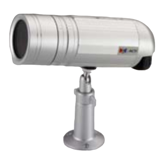
- Page 1 IP Outdoor IR Bullet Camera (with DC 12V / PoE / AC24V) ACM-1430 series Ver. 081016 Hardware User’s Manual...
-
Page 2: Trademarks
PRECAUTIONS Read these instructions All the safety and operating instructions should be read before the product is operated. Heed all warnings All warnings on the product and in the instruction manual should be adhered to. The symbol indicates the following items, please carefully read the description next to each symbol. - Page 3 and can radiate radio frequency energy and, if not installed and used in accordance with the instruction manual, may cause harmful interference to radio communications. Operation of this equipment in a residential area is likely to cause harmful interference in which case the user will be required to correct the interference at his own expense.
-
Page 4: Table Of Contents
Table of Contents PRECAUTIONS________________________________________________ 0-1 Trademarks ________________________________________________________________ 0-1 Liability ___________________________________________________________________ 0-1 FCC/CE Regulation __________________________________________________________ 0-1 INTRODUCTION ______________________________________________ 1-1 Package Contents _______________________________________________ 1-1 Features and Benefits ____________________________________________ 1-2 Safety Instructions ______________________________________________ 1-4 Physical Description _____________________________________________ 1-6 Basic Connections _______________________________________________ 1-8 Installation Procedure ___________________________________________ 1-9 1.6.1 Loosen the screws, and remove camera back _______________________________ 1-9 1.6.2... -
Page 5: Introduction
INTRODUCTION 1.1 Package Contents ACM-1430 series Power Adaptor (Option) (DC12V / PoE / AC24V) Product CD Terminal Block for Power Warranty Card... -
Page 6: Features And Benefits
1.2 Features and Benefits This IP device is a cutting-edge digital video transmission device. It can compress and transmit real time images with outstanding images quality (D1, 720x480) at reasonable bandwidth through a standard TCP/IP network. That is because it is Ethernet ready and has the powerful ARM9 SoC and the MPEG-4 compression ASIC inside. - Page 7 utilize the existing PC to be a digital video recorder. Schedule recording and manual recording keep every important image recorded in the local hard disk. Reliable and accurate motion detection with instant warning makes you responsive in every condition. Quick and simple search and playback function lets you easily find the images you want.
-
Page 8: Safety Instructions
1.3 Safety Instructions Don’t use the power supply with other voltages This device is likely to be damaged or damage other equipments / personnel, if you use a power supply with different voltage than the one included with this device. All warranty of this product will be voided in the situations above. - Page 9 If the video product does not operate normally by following the operating Instructions in this manual. Adjust only those controls that are covered by the instruction manual as an improper adjustment . Other controls may result in damage and will often require extensive work by a qualified technician to restore the video product to its normal operation.
-
Page 10: Physical Description
1.4 Physical Description Power Input If your power input is DC12V. Please follow the description on the connector to connect to power. NAME DESCRIPTION DC Power Input Ground Pin If your power input is AC24V. Please follow the description on the connector to connect to power. - Page 11 Audio Input / Output & Video Output The IP device supports audio input and output, and video output with terminal block. Reset Button Step 1: Switch off IP device by disconnecting the power cable Step 2: Press and continue to hold the Reset Button. Reconnect the power cable while continuing to hold the reset button.
-
Page 12: Basic Connections
1.5 Basic Connections Follow the procedures below to connect the IP device to the respective apparatuses. 1. Connect an analog monitor to IP device video out (BNC connector). 2. Connect the power adaptor to IP device 3. Connect IP device’s ethernet port to an Ethernet (RJ45 connectors). If your IP device has PoE built-in, you can regard it as a PD and connect it directly to a PSE device like PoE switch. -
Page 13: Installation Procedure
1.6 Installation Procedure 1.6.1 Loosen the screws, and remove camera back 1.6.2 Connect cables through conduit hole... -
Page 14: I/O Connecting
1.6.3 I/O connecting Reference section 1.4 Physical Description for detail spec of I/O connecting. 1.6.4 Install camera back and tighten the screws 1-10... -
Page 15: Loosen The Screws And Remove Sunshield
1.6.5 Loosen the screws and remove sunshield 1.6.6 Install the camera onto bracket 1-11... -
Page 16: Rotate Camera Box Counter-Clockwise To Remove Camera Cover
1.6.7 Rotate camera box counter-clockwise to remove camera cover 1.6.8 Adjust the focus / zoom / dip switch - Focus adjust lever - Zoom adjust lever 1-12... -
Page 17: Install Sunshield And Camera Cover Back
1.6.9 Install sunshield and camera cover back 1-13... -
Page 18: Product Specification
1.7 Product Specification 1-14...
Need help?
Do you have a question about the ACM-1430 series and is the answer not in the manual?
Questions and answers