Table of Contents
Advertisement
Installation Guide
XX214-00-05
Surveyor® HD Series
Network Camera Domes
Vicon Industries Inc.
Tel: 631-952-2288 Fax: 631-951-2288 Toll Free: 800-645-9116
24-Hour Technical Support: 800-34-VICON (800-348-4266) UK: 44/(0) 1489-566300
Vicon Industries Inc. does not warrant that the functions contained in this equipment will meet your requirements or that the
operation will be entirely error free or perform precisely as described in the documentation. This system has not been designed
to be used in life-critical situations and must not be used for this purpose.
www.vicon-security.com
Document Number: 8009-8214-00-05
Issued: 1213
Product specifications subject to change without notice.
Copyright © 2013 Vicon Industries Inc. All rights reserved.
Advertisement
Table of Contents

Related Manuals for Vicon SN118C


Summary of Contents for Vicon SN118C
- Page 1 24-Hour Technical Support: 800-34-VICON (800-348-4266) UK: 44/(0) 1489-566300 Vicon Industries Inc. does not warrant that the functions contained in this equipment will meet your requirements or that the operation will be entirely error free or perform precisely as described in the documentation. This system has not been designed to be used in life-critical situations and must not be used for this purpose.
-
Page 2: Fcc Notice
FCC Notice Note: Complies with Federal Communications Commission Rules & Regulations Part 15, Subpart B for a Class A digital device. WARNING This equipment generates and uses radio frequency energy and if not installed and used properly, that is, in strict accordance with the manufacturer’s instruction, may cause interference to radio and television reception. -
Page 3: Important Safeguards - Outdoor Use
6. Cleaning - (Do not use caustic, abrasive or aerosol The product shows a significant change in performance. cleaners) 21. Replacement Parts - Use only Vicon specified replacement For units that CAN BE DISCONNECTED from the power parts or an approved equivalent to prevent unit damage and source, use a damp cloth for cleaning. -
Page 4: Chapter 1 Introduction
General Information Chapter 1 Introduction This chapter provides general information about the Surveyor HD Network Dome. Refer to the end of this chapter for the organization of the rest of this manual. The chapter consists of the following topics: Topic Page General Information Model Tables... -
Page 5: General Information
H.264 or M-JPEG compression. The dome supports ONVIF open architecture connectivity to enable integration into third party Video Management Systems (VMS), including Vicon’s ViconNet. The Surveyor HD is designed for easy installation and serviceability. The entire drive assembly simply snaps into the housing. When removed, the mechanism retains all programmed functions in its on-board memory. - Page 6 Add a –FM to the model number for a multi-mode fiber version and a –FS to the model number for a single mode fiber model. Table 2: Power Table Power Current Rating Model Number (A) (see notes) SN118C, SN118C-FM SN118C-FS 1.0 (1) SN118D, SN118D-FM, SN118D-FS 1.0 (1) SN118W, SN118W-FM, SN118W-FS 2.2 (2) SN118M, SN118M-FM, SN118M-FS 2.2 (2) SN220C, SN220C-FM SN220C-FS 1.0 (1)
-
Page 7: Organization Of This Manual
Surveyor HD Network Dome Maintenance and Reference: Describes basic system maintenance, reference information, shipping instructions and technical specifications for the camera dome. Note Always check the Vicon website, www.vicon-security.com, for the latest updated manuals. XX214-00 Surveyor HD Network Dome... -
Page 8: Chapter 2 Installation
Installation Chapter 2 Installation This chapter provides installation information for the Surveyor HD Network Dome. The chapter consists of the following topics: Topic Page Installation Quick Installation Detailed Installation Surveyor HD Network Dome XX214-00... -
Page 9: How To Use This Manual
Chapter 2 Installation Installation Caution This unit should only be installed by a qualified technician using common hand tools and approved materials and wiring methods in accordance with the National Electrical Code ANSI/NFPA 70, state and local wiring codes. All interconnecting equipment or accessories must be UL Listed. -
Page 10: Accessory Kits
Unpacking All Vicon equipment is tested and inspected before leaving the factory. It is the carrier’s responsibility to provide suitable delivery. Inspect the cartons upon delivery and, if damage is present, make detailed notes on the carrier’s bill. - Page 11 Chapter 2 Installation Components All Surveyor HD units are comprised of an Enclosure/Housing, a Camera Drive, a Shroud and a Lower Dome. Enclosure The enclosure is a metal shell that houses the camera drive for the in-ceiling model. A safety cord and clip are provided to connect to the camera drive during installation.
- Page 12 Installation Lower Dome The lower dome is an assembly comprised of a 5.98 inch (152 mm) diameter acrylic plastic shell, a trim ring and a safety cord. Lower domes for indoor versions come are smoked; chrome or gold finishes are available as special options.
-
Page 13: Mac Address
Chapter 2 Installation MAC Address XX214-00 Surveyor HD Network Dome... -
Page 14: Quick Installation
Installation Quick Installation Choose the installation type based on the specific unit purchased (In-Ceiling, Indoor or Outdoor/High-Impact Pendant). In-Ceiling Installation Surveyor HD Network Dome XX214-00... - Page 15 Chapter 2 Installation Pendant Installation XX214-00 Surveyor HD Network Dome...
-
Page 16: Detailed Installation
Installation Detailed Installation Select a location for the installation of the Surveyor HD. Be sure the area around the selected location is clear of obstacles (such as steel beams, headers, pipes, electrical wiring, etc.) that could interfere with the mounting of the camera dome and that the location can support the weight of the unit. - Page 17 2-10 Chapter 2 Installation The accessory kit contains the removable screw terminal blocks to be used for all connections in this installation. The ceiling material must provide a surface of suitable strength for the Surveyor HD weight of 4.6 lb (2.1 kg) on the area of the two flippers. Refer to the Optional Independent Support sub-section for installations requiring additional support.
- Page 18 2-11 Installation Note There should be minimal wire slack at all connection points. Skip step 6 for cable use with flexible conduit. 7. Loosen flipper screws and remove enclosure from ceiling. Slide cables back through fitting until terminal blocks are flush with the bottom of enclosure, approximately 9 inches (229 mm).
- Page 19 2-12 Chapter 2 Installation 12. Lift the lower dome up to the Surveyor HD and line up the 2 molded tabs on the lower dome with the 2 recesses on the inner enclosure. There are only 2 ways to align it. 13.
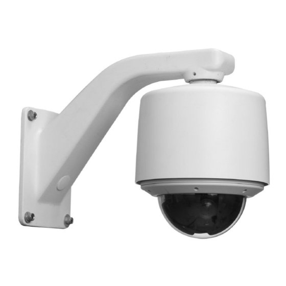
- Page 20 Pendant Mount Models The indoor, outdoor and high-impact pendant models mount on a variety of Vicon mounts or a 1.5-inch vertical pipe with an appropriate coupling. The pipe is a standard 1.5-inch NPT type and must be oriented vertically so the Surveyor HD can effectively hang from the pipe.
- Page 21 2-14 Chapter 2 Installation removed if necessary by snapping it out of the hinge after rotated to the 90º downward position.) Refer to figure below. 4. On outdoor/high-impact versions, apply the provided anti-seize lubricant to the first 2-3 unpainted threads of the housing. 5.
- Page 22 2-15 Installation 8. Remove terminal blocks from the accessory kit. The 2-pin (TB2) is for power, the 4-pin (TB5) is for control/relay and the 8-pin is for alarms. 9. Slide excess cable back up into the mount/pipe so that cable length is flush with the bottom of the housing, approximately 8 - 9 inches (203 - 229 mm).
- Page 23 2-16 Chapter 2 Installation Warning Cables having excessive slack can cause damage to the Surveyor HD when installed into the housing. 15. Push the camera drive straight up into the housing until it snaps into the housing. Do not use excessive force. In the event that it does not snap easily, remove the Surveyor HD and verify proper cabling.
-
Page 24: Chapter 3 Wiring
Wiring Chapter 3 Wiring This chapter will describe how to wire, configure and operate the Surveyor HD Network Dome. The chapter consists of the following topics: Topic Page Wiring the Surveyor HD Network Dome ............3-2 Typical Relay and Alarm Connections ............3-3 Installing the Cables .................. - Page 25 Chapter 3 Wiring Wiring the Surveyor HD Network Dome Wiring is done with runs of cable for power, network and control. Optional wiring can be installed for the alarm input. Refer to the Technical Information section for all electrical requirements. Power Power cables carry AC power and are usually a two-conductor type ranging in size from 20 to 16 AWG.
-
Page 26: Typical Relay And Alarm Connections
Wiring Typical Relay and Alarm Connections Alarm input and relay output type signals are also carried on individually- shielded twisted-pair cable sets. The signals are defined in the following descriptions. Note The twisted-pair cable should have a wire gauge (AWG) of 24-16 and a category type of 2, 3, 4, 5 or better. - Page 27 Chapter 3 Wiring The “active” state can be programmed through the Surveyor HD web browser interface. These signals are connected to terminal block TB1. Alarm signals can be programmed for their status (enabled/disabled), active level definition (high/low), action/reset function (none, preset, aux on, aux off or tour), acknowledgment mode (automatic, momentary or manual) and report status (active/inactive).
-
Page 28: Installing The Cables
Wiring Installing the Cables Warning Disable the AC power to prevent installer injury and damage to the unit. Cables are installed using 2 different methods, depending on the installation type. For the in-ceiling installation, cables are routed from above the ceiling through a conduit fitting on the enclosure to the customer interface board. - Page 29 Chapter 3 Wiring For an Indoor or Outdoor/High-Impact Pendant Model Installation Refer to the Figure at the end of this section for customer interface board connections. 1. Route each cable from the inside top of the housing. 2. Remove terminal blocks from the accessory kit. The 2-pin is for power (TB2), the 4-pin is for relays (TB5) and the 8-pin is for alarms (TB1).
- Page 30 Wiring Table 3: Wiring Connections CONNECTOR/PIN CONNECTOR TYPE CONNECTOR/PIN LABEL SIGNAL NAME NUMBER TERMINAL BLOCK POWER (TB2) TB2-1 TB2-2 Neutral TERMINAL BLOCK ALARM (TB1) TB1-1 ALARM 1 Alarm I/O 1 TB1-2 Ground TB1-3 ALARM 2 Alarm I/O 2 TB1-4 Ground TB1-5 ALARM 3 Alarm I/O 3...
-
Page 31: Setting The Dip Switches
Chapter 3 Wiring Setting the DIP Switches There are two DIP switches that must be set on the Surveyor HD. One is on the Communications Interface (CI) board and one on the Main board. SW1 4-position DIP switch is on the Communication Interface (CI) board. For SW1 all poles should be set to OFF (default). - Page 32 Wiring Position 4 – Unused (set to OFF) Position 5 – Unused (set to OFF) Position 6 – Set NTCIP. OFF = Default Position, NTCIP Enabled. ON = NTCIP disabled. Position 7 – Set password. OFF = Default Position. ON = Reset to default password (password or 1234);...
- Page 33 3-10 Chapter 3 Wiring This page left intentionally blank XX214-00 Surveyor HD Network Dome...
-
Page 34: Chapter 4 Operation, Maintenance And Reference
This chapter provides Operation instructions, Maintenance information, cable recommendations and technical specifications for the Surveyor HD Network Dome. The chapter consists of the following topics: Topic Page Operation Maintenance Shipping Instructions Technical Specifications Vicon Standard Equipment Warranty 4-11 Surveyor HD Network Dome XX214-00... -
Page 35: Operation
The Surveyor HD Camera Dome operates on an Onvif compliant platform that allows it to work with any Onvif compliant Video Management System (VMS), including Vicon’s ViconNet. Refer to the documentation for those operating systems to setup the Surveyor HD. After the camera dome is configured according to the requirements for the specific video management system, it is controlled through the Web Browser interface. -
Page 36: Maintenance
Operation, Maintenance and Reference Maintenance The Surveyor HD requires no scheduled maintenance; however, the lower domes require occasional cleaning. The clear and smoked domes are referred to as acrylic type domes. The chrome and gold domes are referred to as metallized type domes. All domes require careful handling and occasional cleaning. -
Page 37: Care And Cleaning Of Metallized Domes
Operation, Maintenance and Reference e Care and Cleaning of Metallized Domes 1. Always handle the lower dome by the flange and avoid touching the inside surface, as acid in a fingerprint can etch the internal coating. Use the recommended cleaning procedure in Step 4. 2. -
Page 38: Shipping Instructions
Shipping Instructions Use the following procedure when returning a unit to the factory: 1. Call or write Vicon for a Return Authorization (R.A.) at one of the locations listed below. Record the name of the Vicon employee who issued the R.A. -
Page 39: Network Cable
Operation, Maintenance and Reference e Network Cable Caution Careful selection of proper cable is essential to obtain the best performance. Vicon assumes no responsibility for poor performance when cables other than the recommended types, or equivalent, are used. Vicon recommends using shielded cable. Materials Use pure copper stranded conductors to obtain a low DC resistance. -
Page 40: Technical Specifications
1280 x 720 @ 30 fps. 2 megapixel version: 1920 x 1080 @ 30 fps. Programming Interface: ONVIF, NTCIP,or Vicon API. Protocols: IP, HTTP, RTSP/RTP, DNS client, FTP, SMTP, PPPoE, TCP/IP, DHCP, UDP, Multicast, NTP, DDNS, IGMP, ARP, SOAP, WSDL, WS- Discovery. - Page 41 Operation, Maintenance and Reference e Sensitivity: 1.3 megapixel version: Color: 0.18 fc (1.8 lux). B&W: 0.002 fc (0.02 lux) at 50 IRE, f/1.6, 1/4s, IRcf Off. IR cut filter is removable. 2 megapixel version: Color: 0.16 fc (1.6 lux). B&W: 0.004 fc (0.04 lux) at 50 IRE, f/1.6, 1/8s, IRcf Off. IR cut filter is removable.
- Page 42 Operation, Maintenance and Reference Autotour Capabilities: 2 autotours available with 256 pan, tilt and zoom functions per autotour. Programming is done in real time with joystick and push buttons. Sectoring: 16 maximum, programmable for size and titling. Sectors have the capability to be blanked out.
- Page 43 4-10 Operation, Maintenance and Reference e Rain/Wind: Outdoor: Heavy rain up to 4 in./hr at winds up to 90 mph, when mounted on standard Vicon wall mount. Compliance: International Protection (IP) Ratings: Outdoor/Impact-Resistant: IP66, NEMA 4X; NEMA TS2-2003 V02.06. Indoor Pendant: IP52.
-
Page 44: Vicon Standard Equipment Warranty
“autopan” or “tour” modes of operation. Such continuous operation is outside the scope of this warranty. Any product sold as “special” or not listed in Vicon’s commercial price list: One year from date of original retail purchase. - Page 45 Vicon Industries Inc. For office locations, visit the website: www.vicon-security.com...
Need help?
Do you have a question about the SN118C and is the answer not in the manual?
Questions and answers