Table of Contents
Advertisement
Installation Guide
XX282-10-01
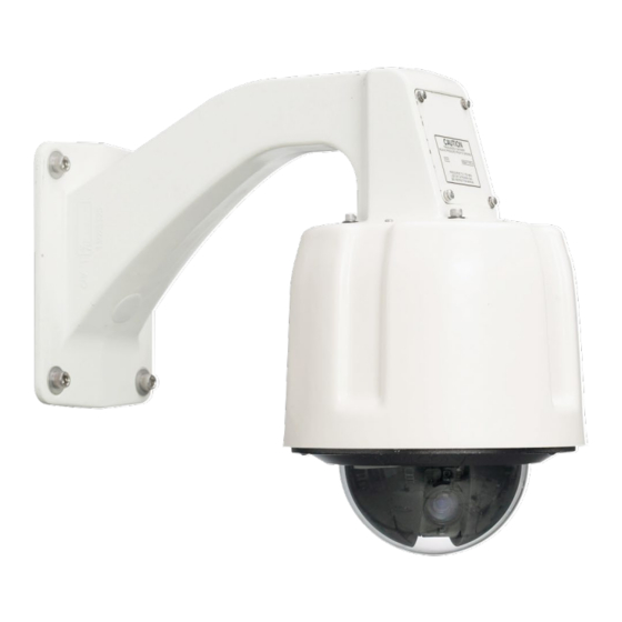
Surveyor® MKII Series
Pressurized Network
Camera Domes
Vicon Industries Inc.
Tel: 631-952-2288 Fax: 631-951-2288 Toll Free: 800-645-9116
24-Hour Technical Support: 800-34-VICON (800-348-4266) UK: 44/(0) 1489-566300
Vicon Industries Inc. does not warrant that the functions contained in this equipment will meet your requirements or that the
operation will be entirely error free or perform precisely as described in the documentation. This system has not been designed
to be used in life-critical situations and must not be used for this purpose.
www.vicon-security.com
Document Number: 8009-8282-10-01
Issued: 117
Product specifications subject to change without notice.
Copyright © 2017 Vicon Industries Inc. All rights reserved.
Advertisement
Table of Contents

Related Manuals for Vicon Surveyor MKII Series XX282-00-01


Summary of Contents for Vicon Surveyor MKII Series XX282-00-01
- Page 1 24-Hour Technical Support: 800-34-VICON (800-348-4266) UK: 44/(0) 1489-566300 Vicon Industries Inc. does not warrant that the functions contained in this equipment will meet your requirements or that the operation will be entirely error free or perform precisely as described in the documentation. This system has not been designed to be used in life-critical situations and must not be used for this purpose.
-
Page 2: Chapter 1 Introduction
Introduction Chapter 1 Introduction This chapter provides general information about the Surveyor MKII Pressurized Network Dome. Refer to the end of this chapter for the organization of the rest of this manual. The chapter consists of the following topics: Topic Page General Information Model Tables... -
Page 3: General Information
H.264 or M-JPEG compression. The dome supports ONVIF open architecture connectivity to enable integration into third party Video Management Systems (VMS), including Vicon’s Valerus and ViconNet. The Surveyor MKII is designed for easy installation and serviceability. The entire drive assembly simply snaps into the housing. When removed, the mechanism retains all programmed functions in its on-board memory. -
Page 4: Organization Of This Manual
Introduction Organization of this Manual Chapter Description Introduction: Provides general information about the Surveyor MKII Pressurized Network Dome Installation: Describes how to install the Surveyor MKII Pressurized Network Dome and wiring instructions Configuration and Operation: Describes how to, configure and operate the Surveyor MKII Pressurized Network Dome Maintenance and Reference: Describes basic system maintenance, reference information, shipping instructions... -
Page 5: Chapter 2 Installation
Chapter 2 Installation Chapter 2 Installation This chapter provides installation information for the Surveyor MKII Pressurized Network Dome. The chapter consists of the following topics: Topic Page Installation ...................... 2-6 Quick Installation ..................2-10 Detailed Installation ..................2-11 Uninstalling ....................2-32 Surveyor MKII Pressurized Network Dome... -
Page 6: How To Use This Manual
Installation Installation Caution This unit should only be installed by a qualified technician using common hand tools and approved materials and wiring methods in accordance with the National Electrical Code ANSI/NFPA 70, state and local wiring codes. All interconnecting equipment or accessories must be UL Listed. Any mention in this manual of alarm inputs/outputs have not been evaluated by UL to be used for burglar alarm functionality. -
Page 7: Accessory Kits
Optionally, a 23-pin prefabricated cable assembly may be purchased separately for ease of wiring. Unpacking All Vicon equipment is tested and inspected before leaving the factory. It is the carrier’s responsibility to provide suitable delivery. Inspect the cartons upon delivery and, if damage is present, make detailed notes on the carrier’s bill. - Page 8 Installation Note By default, when the pressure in the housing dips below 1/2 psig an On Screen Display message appears stating “Low Pressure Warning.” Alternatively, this alarm warning may be sent to the CPU by enabling the alarm in the camera dome’s menu. When this is activated, the On Screen Display message will not appear.
-
Page 9: Mac Address
Chapter 2 Installation MAC Address Each IP camera has a unique MAC address. This information is essential in the camera configuration process. Before starting installation, make a record of the IP address and location of the camera. The MAC address is located as shown in the illustration below, under the connector on the mechanism. -
Page 10: Quick Installation
Installation Quick Installation Surveyor MKII Pressurized Network Dome... -
Page 11: Detailed Installation
Be sure to remove the black foam that keeps the camera in place in the mechanism during shipping. Wall Mount Method Use this method to install, wire and configure a unit with a Vicon wall mount. Refer to the Figure below as required. Wall Mount Installation Installing the Wall Mount 1. - Page 12 2-11 Installation Note Verify there are no obstacles behind the surface before drilling. 3. Place a bead of silicone sealant around the wall mount mounting flange, press it to the surface and line up the flange holes with drilled holes. Install the appropriate 3/8 in.
-
Page 13: Pipe Mount Method
2-12 Chapter 2 Installation Pipe Mount Method Use this method to install, wire and configure a pipe mounted unit. Refer to Figure below as required. Installing the Pipe Mount Select a suitable mounting location and verify that the site wiring is present. - Page 14 2-13 Installation Installing the 23-Pin Connector Assembly (If the prefabricated 23-pin cable assembly is used.) 6. Use the 23-pin cable assembly purchased separately. It should resemble the assembly of Figure below. a. Identify the cables required for attaching to the 23-pin connector assembly.
- Page 15 2-14 Chapter 2 Installation Note The wire color code may not match the Figure. Verify each wire is labeled with a function. DO NOT remove the labels. Use the wire labels for absolute reference. Wiring and Assembling the 23-Pin Connector (Using the discrete 23-pin connector with crimp pins provided.) 7.
- Page 16 2-15 Installation d. Prepare each cable by stripping back the jacket and individual wire covering to the dimensions shown in preceding Figure. e. Identify each wire on the site installed cables and label them (A, B, C, D….etc.) in accordance with the labels on the 23-pin connector assembly wires.
-
Page 17: Housing Connections
2-16 Chapter 2 Installation Route the 23-pin connector assembly through the service cover and out the back of the wall mount. Leave the 23-pin connector assembly and an excess of about 2 in. (51 mm) of cable at the service opening. Inspect the top of the housing assembly and verify that there is no debris on the gasket area. - Page 18 2-17 Installation Preparing the Camera Drive Open the box containing the camera drive assembly and CI board and remove them. Install the Customer Interface (CI) board, which is packed separately under the mechanism, into the housing. Make connections to the CI board using 23-pin configured cable.
- Page 19 2-18 Chapter 2 Installation Attach the trim ring lanyard to the trim ring assembly and mate it to the housing by aligning the housing holes with the trim ring/lower dome holes. Install the eight (8) screws and tighten only with a torque wrench set for 15-in.
-
Page 20: Communication Ports
2-19 Installation Warning Do not use any gas type other than dry Nitrogen. The use of Shop Air can introduce moisture into the housing assembly that can damage it over time. Proceed to the Operation section of this manual. Communication Ports If using NTCIP protocol, communicate to the Surveyor MKII using ports 3000/UDP or 3001/TCP. -
Page 21: Accessing The Sd Card
2-20 Chapter 2 Installation Accessing the SD Card The SD card slot is on the camera board right under the lens block. To access the card, remove the cover by removing the two (2) screws securing the shroud in place. Press the card to release it from the slot. To insert the card back into the slot, press it into the slot until it clicks to lock it in place. -
Page 22: Chapter 3 Configuration And Operation
3-21 Configuration and Operation Chapter 3 Configuration and Operation This chapter will describe how to wire, configure and operate the Surveyor MKII Pressurized Network Dome. The chapter consists of the following topics: Topic Page Typical Relay and Alarm Connections 3-34 Configuring and Operating the Pressurized Surveyor MKII Network Dome 3-36... -
Page 23: Typical Relay And Alarm Connections
3-22 Chapter 3 Configuration and Operation Typical Relay and Alarm Connections Alarm input and relay output type signals are also carried on individually- shielded twisted-pair cable sets. The signals are defined in the following descriptions. Note The twisted-pair cable should have a wire gauge (AWG) of 24-16 and a category type of 2, 3, 4, 5 or better. - Page 24 3-23 Configuration and Operation Figure below. The relay output contact can be programmed for its power-on state definition (on/off) and output type definition (momentary or latching). There is one relay output dry contact located on terminal block J12. Connect the circuit to be switched to the connector pins labeled RELAY C (relay common) and RELAY NC or RELAY NO for a normally closed or normally open connection, respectively.
-
Page 25: Configuring And Operating The Pressurized Surveyor Mkii Network Dome
3-24 Chapter 3 Configuration and Operation Configuring and Operating the Pressurized Surveyor MKII Network Dome Following the completion of the installation, the pressurized Surveyor MKII is setup and operated through a web browser interface. Refer to the Web Browser instruction manual for detailed information on camera configuration. Surveyor MKII Pressurized Network Dome... - Page 26 Surveyor MKII Pressurized Network Dome. The chapter consists of the following topics: Topic Page Operation 4-38 Maintenance 4-39 Shipping Instructions 4-28 Network Cable 4-41 Technical Specifications 4-42 Vicon Standard Equipment Warranty 4-45 Surveyor MKII Pressurized Network Dome...
-
Page 27: Operation
The Pressurized Surveyor MKII Camera Dome operates on an Onvif compliant platform that allows it to work with any Onvif compliant Video Management System (VMS), including Vicon’s Valerus and ViconNet. Refer to the documentation for those operating systems to setup the Surveyor MKII. -
Page 28: Maintenance
4-27 Operation, Maintenance and Reference Maintenance The Pressurized Surveyor MKII requires no scheduled maintenance; however, the lower domes require occasional cleaning. All domes require careful handling and occasional cleaning. Care and Cleaning of Smoked and Clear Acrylic Domes 1. Always handle the lower dome by the flange and avoid touching the inside surface. -
Page 29: Shipping Instructions
Shipping Instructions Use the following procedure when returning a unit to the factory: 1. Call or write Vicon for a Return Authorization (R.A.) at one of the locations listed below. Record the name of the Vicon employee who issued the R.A. -
Page 30: Network Cable
Network Cable Caution Careful selection of proper cable is essential to obtain the best performance. Vicon assumes no responsibility for poor performance when cables other than the recommended types, or equivalent, are used. Materials Use pure copper stranded conductors to obtain a low DC resistance. The preferred insulation and cable jacket is Polyvinyl chloride (PVC). -
Page 31: Technical Specifications
10 concurrent sessions maximum Video Output: 1920 x 1080 @ 30 fps Programming ONVIF or Vicon API Interface: Protocols: IPv4/IPv6, TCP, UDP, IGMP, DHCP, FTP, SNMP(v3), SMTP, NTP, RTP, RTSP, RTCP, HTTP, HTTPS, TSL, SSL, 802.1X, QoS, PPPoE, DNS, ARP, ICMP,... - Page 32 4-31 Operation, Maintenance and Reference Angle of View: Horizontal: 63.4° wide, 2.3° tele Operational Drive Type: Electrical motorized pan and tilt with electronic control Pan View: 360° continuous Tilt View: -2.5 to 90° Pan Speed: 400°/sec, max Tilt Speed: 150°/sec, max Optical 1.8 sec, tele to wide Zoom/Focus Speed:...
-
Page 33: Mechanical And Environmental
4-32 Chapter 4 Operation, Maintenance and Reference Mechanical and Environmental Operating Pressure: 1 - 5 psi (0.07 - 0.34 atm or bars) maximum Pressurization: Schraeder type valve used to fill and drain housing with dry nitrogen gas. Relief valve automatically relieves pressure at 5 - 7 psi (0.34 - 0.48 atm). Leakage <2 psi per year. -
Page 34: Vicon Standard Equipment Warranty
“autopan” or “tour” modes of operation. Such continuous operation is outside the scope of this warranty. 11. Any product sold as “special” or not listed in Vicon’s commercial price list: One year from date of original retail purchase. - Page 35 Chapter 4 Operation, Maintenance and Reference media or batteries) (g) to products that have been purchased “as is” and Vicon the seller or the liquidator expressly disclaim their warranty obligation pertaining to the product, (h) to any non-Vicon hardware product or any software...
- Page 36 VICON INDUSTRIES INC. For office locations, visit the website: www.vicon-security.com...
Need help?
Do you have a question about the Surveyor MKII Series XX282-00-01 and is the answer not in the manual?
Questions and answers