Table of Contents
Advertisement
Quick Links
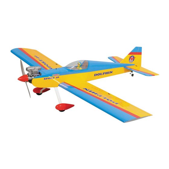
I n s t r u c t i o n M a n u a l
SPECIFICATION
- Wingspan: 1600mm (63 in)
- Length: 1285mm (50.5 in)
- Flying weight: 2800-3200 gr
- Wing area: 40.1 dm2
- Wing loading: 78g/dm2
- Wing type: Naca airfoils
- Covering type: Genuine ORACOVER®
- Spinner size: Plastic 58mm (included)
- Radio: 4 channel minimum (not included)
- Servo: 5 standard servo: 2 aileron; 1 elevator;
1 rudder; 1 throttle (not included)
- Recommended receiver battery:
4.8-6V / 800-1200mAh NiMH (not included)
- Servo mount: 21mm x 42 mm
- Propeller: suit with your engine
- Engine: .46-.55 / 2-stroke or .52/4-stroke
glow engine (not included)
We wish you many enjoyable flights with your plane and one again thank you for your choosing a Phoenix Model products.
- Motor: brushless outrunner 1000-1400 W,
480 KV (not included)
- Gravity CG: 75 mm (2.9 in) Back from the
leading edge of the wing, at the fuselage
- Control throw Ailerons: Low: 11mm up/down,
10% expo; High: 14mm up/down, 10% expo
- Control throw Elevators: Low: 11mm up/down,
12% expo; High: 14mm up/down, 12% expo
- Control throw Rudder: Low: 25mm right/left,
15% expo; High: 40mm right/left, 15% expo
- Experience level: Intermediate
- Plane type: Low wing sport
RECOMMENDED MOTOR AND BATTERY SET UP
- Motor: RIMFIRE .46-.55 (not included)
- Lipo cell: 6 cells / 4000 – 5500mAh (not included)
- Esc: 50-80A (not included)
Advertisement
Table of Contents

Related Manuals for Phoenix Model Dolphin


Summary of Contents for Phoenix Model Dolphin
- Page 1 - Lipo cell: 6 cells / 4000 – 5500mAh (not included) - Engine: .46-.55 / 2-stroke or .52/4-stroke glow engine (not included) - Esc: 50-80A (not included) We wish you many enjoyable flights with your plane and one again thank you for your choosing a Phoenix Model products.
-
Page 2: Table Of Contents
Thank you for purchasing Phoenix Model products. With over 20 years experience in production and fly testing, Phoenix Model is committed to bring the best quality products and good service to customers. Along with a team of creative engineers and skilled workers, we will always accompany with customers by our great experiences, fully enthusiasm... -
Page 3: Warranty
Vacuum the parts and the work area to assemble and use this. thoroughly after working with fiberglass parts. In that Phoenix Model has no control over the final assembly or material used for final assembly, Phoenix SUGGESTION Model is not responsible for loss of use , or other incidental or consequential damages. -
Page 4: Flight Warnings
Instruction Manual DOLPHIN FLIGHT WARNINGS ADHESIVES AND REQUIRED TOOLS When ready to fly, first extend the transmitter aerial. Thin CA Switch on the transmitter. 30-minute epoxy Switch on the receiver. 6-minute epoxy Check that the wings are correctly fitted to the Threadlocker thread locking cement fuselage. - Page 5 Instruction Manual DOLPHIN • Officially designated AMA Air Show Teams (AST) are authorized to use devices and practices as defined within the Team AMA Program Document. (AMA Document #718.) (j) Not operate a turbine-powered aircraft, unless in compliance with the AMA turbine regulations. (AMA Document #510-A.)
-
Page 6: Preparations
Instruction Manual DOLPHIN PREPARATIONS 4. Using the thread as a guide and using masking tape, tape the servo lead to the end of the thread: carefully pull the thread out. When you Use a covering iron with a covering sock on high heat to tighten the covering if necessary. -
Page 7: Installing The Control Horns
Instruction Manual DOLPHIN 4. Plug the aileron servo into the receiver and INSTALLING THE CONTROL HORNS center the servo. Install the servo arm onto the servo. The servo arm should be perpendicular 1. One aileron control horn in positioned on each to the servo and point toward the middle of the aileron. -
Page 8: Wing Assembly
Instruction Manual DOLPHIN Wing Assembly 5) Once the epoxy has cured, trial fit both wing halves together.The center gribs should fit flush *Note* We highly recommend using 30 Minute together with little or no gaps existing. If gaps do Epoxy over faster curing epoxies for several exist, use 220 Grit sandpaper and sand down reasons. -
Page 9: Installing The Wing To The Fuselage
Instruction Manual DOLPHIN 3. Check the fit of the horizontal stabilizer in its slot. Make sure the horizontal stabilizer is square and centered to the fuselage by taking measurements, but don't glue anything yet. Tape 4. With the horizontal stabilizer correctly aligned,... -
Page 10: Vertical Stabilizer Installation
Instruction Manual DOLPHIN 7. After the epoxy has fully cured, remove the 2. Slide the vertical stabilizer into the slot in the masking tape or T-pins used to hold the mounting platform in the top of the fuselage. stabilizer in place and carefully inspect the glue Mark the shape of the fuselage on the left and joints. -
Page 11: Tail Wheel Installation
Instruction Manual DOLPHIN 3. Using a modeling knife, carefully cut out two line from the margin of the hole onto the wheel pant. Just cut only one side of the wheel pant, where the main gear will install. Be sure to make a left and right wheel pant. -
Page 12: Main Gear Installation Installing The Main Landing Gear
Instruction Manual DOLPHIN MAIN GEAR INSTALLATION INSTALLING THE MAIN LANDING GEAR 1. Four nuts have been installed at the factory. 2. Install main landing gear into the fuselage using (4) 4mm x 20mm machine screws and 16mm flat washers provided in the kit. -
Page 13: Fuel Tank Installation
Instruction Manual DOLPHIN Zip tie To carburator To muffler Battery SERVO INSTALLATION FUEL TANK INSTALLATION INSTALLING THE FUSELAGE SERVOS 1. Assemble the fuel tank. 1. Install the rubber grommets and brass collets into the elevator, rudder and throttle servos. Test fit the servos into the servo tray. Trim the tray if necessary to fit your servos 2. -
Page 14: Installing The Elevator Pushrod
Instruction Manual DOLPHIN INSTALLING THE ELEVATOR PUSHROD 1. Locate the pushrod exit slot on the right side and left side of the fuselage. It is located slightly ahead and below the horizontal stabilizer. 2. Carefully cut away the covering material from the slot. -
Page 15: Installing The Rudder Pushrod
Instruction Manual DOLPHIN INSTALLING THE RUDDER PUSHROD 8. Locate one nylon servo arm, and using wire cutters, remove all but one of the arms using a 1. Locate the pushrod exit slot on the left of the 2mm drill bit, enlarge the third hole out from the fuselage. -
Page 16: Final Assembly
Instruction Manual DOLPHIN 3. Slide the adjustable metal connector / servo 2. Wrap the receiver and battery pack in the arm assembly over the plain end of the protective foam to protect them from vibration. pushrod wire. Position the throttle stick and the Use a rubber band or masking tape to hold the throttle trim at their lowest positions. -
Page 17: Lateral Balance
Instruction Manual DOLPHIN 3. If the nose of the plane falls, the plane is heavy nose. To correct this first move the battery 11mm pack further back in the fuselage. If this is not possible or does not correct it, stick small... - Page 18 I/C FLIGHT WARNINGS Always operate in open areas, away Keep all onlookers (especially small from factories, hospitals, schools, THE PROPELLER IS DANGEROUS children and animals) well back from buildings and houses etc. NEVER fly Keep fingers, clothing (ties, shirt the area of operation. This is a flying your aircraft close to people or built sleeves, scarves) or any other loose aircraft, which will cause serious...
- Page 19 I/C FLIGHT GUIDELINES Operate the control sticks on the When ready to fly, first extend the transmitter and check that the control transmitter aerial. surfaces move freely and in the ALWAYS land the model INTO the CORRECT directions. wind, this ensures that the model lands at the slowest possible speed.
Need help?
Do you have a question about the Dolphin and is the answer not in the manual?
Questions and answers