Table of Contents
Advertisement
Quick Links
Advertisement
Table of Contents

Related Manuals for JR Vibe 90 3D


Summary of Contents for JR Vibe 90 3D
-
Page 1: Assembly Instructions
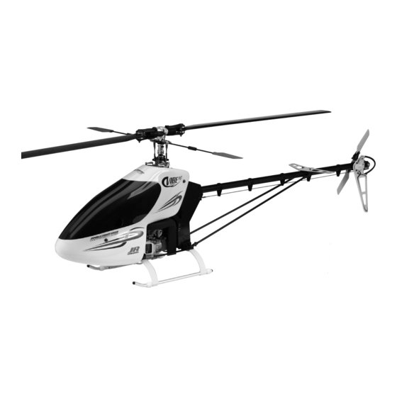
Designed for Today’s Extreme 3D Flying ASSEMBLY INSTRUCTIONS VIBE 90 SPECIFICATIONS Length: 54 in Height: 17.5 in Weight: 10.2-10.5 lb Engine: .80–.91 Heli Bearings: Full Gear Ratio: 8:1:4.83 Main Blade: 700–720 mm (Main rotor blades not included) 7749 7/2005 ®... -
Page 2: Introduction
The radio controlled model helicopter contained in this kit is not a toy but a sophisticated When first opening your Vibe 90 3D kit, you will notice that all of the parts are packaged piece of equipment. This product is not recommended for use by children. Radio and numbered to coordinate with the assembly step numbers of this instruction manual. -
Page 3: Table Of Contents
Upper Servo/Gyro Tray Attachment ....38 Tools Needed to Assemble the JR Vibe 90 3D (not included) ..6 Servo/Switch Harness Installation . -
Page 4: Radio System Requirements (Not Included)
ITEMS REQUIRED TO COMPLETE THE JR VIBE 90 3D 1. RADIO SYSTEM REQUIREMENTS (NOT INCLUDED): • 6-channel or greater R/C helicopter system with 120° or 140° CCPM with 5 servos • 1800mAh or larger receiver battery • Gyro CCPM-Ready JR Radio Systems... -
Page 5: Engine Requirements (Not Included)
RVO1180 (YS) RVO1190 (OS) YS 91 ST4 Heli Engine OS 91 C-Spec Heli Engine 3. BUILDING SUPPLIES (not included): The following items are needed to complete the assembly of the JR Vibe 90 3D: Medium Silicone Fuel High-Speed Tubing (3 ft) -
Page 6: Tools Needed To Assemble The Jr Vibe 90 3D (Not Included)
4. TOOLS NEEDED TO ASSEMBLE THE JR VIBE 90 3D (not included): Nut Drivers: 5 mm, 7 mm Needle-Nose Pliers Scissors Phillips Screwdriver Drill and Drill Bits Small Hammer Hobby Knife Metric Ruler JR Ball Link Sizing Tool Sandpaper (80–120 Grit) Allen Wrenches: 1.5, 2.0, 2.5,... -
Page 7: Hardware Identification
There are a variety of sizes and shapes of hardware included in this kit. All of the hardware, screws, nuts, etc., contained in the Vibe 90 3D kit are Prior to assembly, please be careful to identify each screw by matching it described in the following A, B, C manner: to the full size screw outlines included in each step. -
Page 8: Clutch Bell/Start Shaft Assembly
CLUTCH BELL/START SHAFT ASSEMBLY TEAM TIP: Clean areas with rubbing alcohol to ...2 pcs remove any oil residue before applying threadlock. Socket Head Bolt, 3 x 14 mm Note: ....1 pc Starter Hex Set Screw, 4 x 4 mm Be sure the bearing Adaptor with the 6 mm ID faces upward. -
Page 9: Elevator Arm Assembly
.......1 pc Set Screw, 4 x 4 mm Remove 1 mm from the bottom of this link using a hobby knife Note: Socket Head Bolt, 2.3 x 15 mm Remove JR ® Propo 11 mm ......2 pcs from outside of link using a hobby knife. -
Page 10: T-Arm Lever Assembly
T-ARM LEVER ASSEMBLY Flat Head Screw, 2 x 8 mm (2 pcs) ......8 pc Steel Joint Ball Flat Head Screw, 2 x 8 mm ......8 pcs Steel Joint Ball (6 pcs) Steel Joint Ball Flat Head Screw, 2 x 8 mm (4 pcs) Use Red Threadlock on all screws T-Arm Assembly... -
Page 11: Main Frame Assembly:bearing Block/Clutch Installation
2-1A MAIN FRAME ASSEMBLY: BEARING BLOCK/CLUTCH INSTALLATION Note: Note: ........4 pcs Positon so that bearing faces upward. Prior to assembling the main Socket Head Bolt, 3 x 8 mm frames, sand all edges of the frame using 120 grit sandpaper..4 pcs This will prevent wire chaffing Socket Head Bolt, 3 x 40 mm... -
Page 12: Elevator Arm Installation
2-1B ELEVATOR ARM INSTALLATION Direction of Installation ....4 pcs Standard Range Long Socket Head Bolt, 3 x 8 mm Short Front ..1 pc Rear Socket Head Bolt, 4 x 10 mm .......4 pcs Nylon Lock Nut, 3 mm ......1 pc Spacer, 4 x 5 x 1 mm Use Red Threadlock... -
Page 13: Main Frame Assembly: Cross Member Installation
MAIN FRAME ASSEMBLY: CROSS MEMBER INSTALLATION Cross Member, 24 mm Set Screw, .....2 pcs 3 x 18 mm (2 pcs) Set Screw, 3 x 18 mm TEAM TIP: Do not apply ..1 pc threadlock to bolts unless Cross Member, 32 mm you will proceed through Step 3-8 during this ....3 pcs... -
Page 14: T-Lever Installation
2-3A T-LEVER INSTALLATION Socket Head Bolt, 3 x 28 mm ..2 pcs ........2 pcs Nylon Lock Nut, 3 mm .......2 pcs Mixing Lever Spacer ........2 pcs Nylon Lock Nut, 3 mm (2 pcs) Spacer, 3 x 5 x 1 mm 120 CCPM T-Lever Positions 140 CCPM... -
Page 15: Elevator Control Arm Installation
2-3B ELEVATOR CONTROL ARM INSTALLATION ........2 pcs Set Screw, 4 x 4 mm Elevator Control Arm *Standard Range Direction ........1 pc Nylon Lock Nut, 4 mm Set Screw, 4 x 4 mm ........1 pc Flat Washer, 4 mm Flat Washer, 4 mm Nylon Lock Nut, 4 mm Use Red Threadlock... -
Page 16: Main Frame Assembly: Engine Mount/Cross Member Installation
MAIN FRAME ASSEMBLY: ENGINE MOUNT/CROSS MEMBER INSTALLATION ..6 pcs Socket Head Bolt, 3 x 40 mm ........9 pcs O.S. Engines and YS Engines Socket Head Bolt, 3 x 50 mm ..3 pcs Nylon Lock Nut, 3 mm Engine Mount Direction TEAM TIP: Do not tighten bolts completely at this time. -
Page 17: Main Frame Assembly: Bottom Plate Installation
MAIN FRAME ASSEMBLY: BOTTOM PLATE INSTALLATION Remove a " x 1 " portion of the clear coating from the top of the bottom carbon fiber plate as shown.....2 pcs Socket Head Bolt, 3 x 10 mm ....4 pcs Socket Head Bolt, 3 x 6 mm ....2 pcs Button Head Bolt, 3 x 10 mm Remove a... -
Page 18: Fuel Tank Installation
FUEL TANK INSTALLATION * Cut the tank mounting rubber to ..4 pcs a length as shown from the two 120 mm Socket Head Bolt, 3 x 20 mm pieces included with the kit....2 pcs 210 mm Hex Spacer, 3 x 6 x 6 mm Spacer, 3 x 6 x 6 mm (2 pcs) .......2 pcs Spacer, 3 x 6 x 2 mm... -
Page 19: Front Radio Bed Installation
FRONT RADIO BED INSTALLATION ..........4 pcs Socket Head Bolt 3 x 8mm Socket Head Bolt, 3 x 10 mm (4 pcs) ..........4 pcs Socket Head Bolt 3 x 10 mm ....2 pcs Body Mounting Standoff 24 mm Cross Member 48 mm ..1 pc ...... -
Page 20: Bevel Gear Assembly
3-1B BEVEL GEAR ASSEMBLY Flat Head Bolt, 3 x 6 mm (4 pcs) ...... 4 pcs Flat Head Bolt, 3 x 6 mm Bevel Gear Use Red Threadlock Attach the bevel gear hub as shown. Be sure not to overtighten the four 3 mm bolts as this could distort the bevel gear. -
Page 21: Landing Gear Assembly Installation
LANDING GEAR ASSEMBLY INSTALLATION Nylon Lock Nut, 3 mm (2 pcs) ...2 pcs Socket Head Bolt, 3 x 20 mm ......2 pcs Nylon Lock Nut, 3 mm Landing Struts (2 pcs) ......4 pcs Set Screw, 4 x 4 mm ......4 pcs Flat Washer, 3 mm Flat Washer, 3 mm (4 pcs) Socket Head Bolt, 3 x 20 mm (2 pcs) -
Page 22: Clutch Assembly Attachment
CLUTCH ASSEMBLY ATTACHMENT Socket Head Clutch Assembly Bolt, 4 x 6 mm (2 pcs) ....2 pcs Socket Head Bolt, 4 x 6 mm .....1 pc Flat Head Screw, 2 x 8 mm ......1 pc Steel Joint Ball ......1 pc Hex Nut, 2 mm Use Red Threadlock Flat Head Screw, 2 x 8 mm... -
Page 23: Cooling Fan Shroud Bracket Attachment
COOLING FAN SHROUD BRACKET ATTACHMENT Cooling Fan Shroud Brackets (2 pcs) .....8 pcs Self Tapping Screw, 3 x 12 mm ......8 pcs Flat Washer, 3 mm Note: Do not tighten screws at this time. They will be tightened in Step 3-9. Self Tapping Screw, 3 x 12 mm (8 pcs) Flat Washer, 3 mm (8 pcs) BOLT TIGHTENING ORDER/GEAR MESH ADJUSTMENT... -
Page 24: Cooling Fan Shroud Installation
COOLING FAN SHROUD INSTALLATION ...4 pcs ..6 pcs ....4 pcs Self Tapping Screw, 3 x 12 mm Self Tapping Screw, 2.6 x 8 mm Flat Washer, 3 mm Cooling Fan Shroud (Right) Tighten after right shroud half has been aligned. Glow Plug Opening Cooling Fan (can be enlarged if... -
Page 25: Swashplate Assembly
SWASHPLATE ASSEMBLY ........1 pc Set Screw, 3 x 3 mm Steel Joint Ball (4 pcs) Flat Head Screw, ......4 pcs Steel 2 x 10 mm (4 pcs) Joint Ball Spacer, 2.75 mm (4 pcs) Joint Ball Flat Head Screw, 2 x 10 mm (note correct direction) .........4 pcs Steel Joint Ball... -
Page 26: Swashplate/Washout Assembly Installation
Use caution when connecting the ball links to the swash- plate balls to prevent damage. It is also a good idea to size the ball links with the JR Ball Link Sizing tool prior to attachment. -
Page 27: Rotor Head Installation
ROTOR HEAD INSTALLATION ....1 pc Special Socket Head Bolt, 3 x 22 mm (Long Shank) Main Rotor Head Dampeners Maintenance The main rotor head dampeners should be inspected after 30 to .......1 pc 50 flights and replaced as needed. When replacing the dampeners, Socket Head Bolt, 3 x 12 mm it is also suggested that the thrust bearings be greased using a high speed grease to prolong bearing life. -
Page 28: Flybar Installation
FLYBAR INSTALLATION ......2 pcs Set Screw, 3 x 4 mm Washer, .......2 pcs 4 x 6 x 0.5 mm (2 pcs) Washer, 4 x 6 x 0.5 mm Set Screw, 4 x 4 mm (2 pcs) Flybar, 530 mm Caution: Flybar Control Arm Center the flybar in the seesaw shaft before securing the two... -
Page 29: Swashplate/T-Arm Control Rod Installation
This reduces the size of the the balls. link hole and makes the link fit tighter. JR links are some of the best links available. It is important to note that very little force is needed on the ridges to resize the link. -
Page 30: Tail Drive Shaft Preparation
TAIL DRIVE SHAFT PREPARATION Make sure that all holes are aligned..2 pcs Aluminum Drive Pipe Insert Aluminum Drive Shaft, 794.5 mm Use Green Threadlock Aluminum Drive Shaft Insert Make sure that all holes are aligned. TAIL DRIVE SHAFT ASSEMBLY Set Screw, 3 x 4 mm (2 pcs) .....
Need help?
Do you have a question about the Vibe 90 3D and is the answer not in the manual?
Questions and answers