Table of Contents
Advertisement
Quick Links
PLEASE READ THIS FIRST
Length
Main rotor Dia.
Gear ratio
Tail drive system : Shaft drive
Assembly steps
Step1
Step2
Step3
Step4
Step5
Step6
1,359mm
1,580mm
Tail rotor Dia.
※ 1
T9
10.3 : 1 : 4.65
※ 1 with 710mm main blades ※ 2 not including main blades or battery
VIBE SG E12 FBL Assembly manual
1-2 〜 1-6
1-7 〜 1-9 deleted
2-4、2-5
2-9 deleted
2-10 , 2-11
3-1
3-3
PITCH JIG ASSEMBLY
4-1 , 4-4
4-6
4-9
4-11
5-3、5-4
6-1
Specifications
Height
406mm
288mm
Control System 120 ° CCPM
Ito Edition Supplemental manual
CHOICE
SUPPLEMENTAL MANUAL
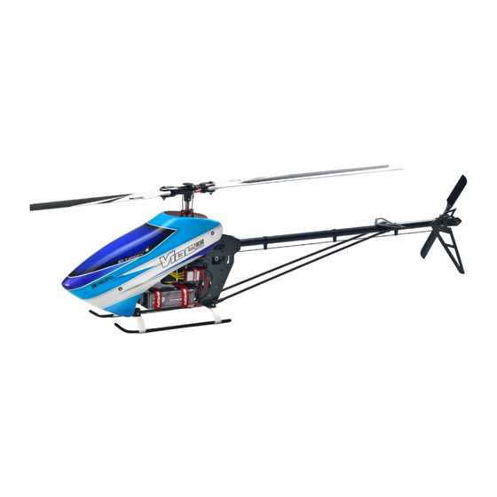
The photo depicts an assembled model
Width
Gross weight
※ 2
1-1
2-1 〜 2-3
2-6 〜 2-8
2-12、2-13
3-2
3-4 〜 3-8
4-5
4-7、4-8
4-10
4-12
5-1、5-2
6-2
182mm
3,600g 〜
Advertisement
Table of Contents

Related Manuals for JR vibe e12 sg fbl


Summary of Contents for JR vibe e12 sg fbl
- Page 1 PLEASE READ THIS FIRST CHOICE SUPPLEMENTAL MANUAL The photo depicts an assembled model Specifications Length 1,359mm Height 406mm Width 182mm Main rotor Dia. 1,580mm Tail rotor Dia. 288mm Gross weight 3,600g 〜 ※ 1 ※ 2 Gear ratio 10.3 : 1 : 4.65 Control System 120 °...
- Page 2 MOTOR MOUNT AND PINION GEAR INSTALLATION ※ T10 and T11 are also available as optional parts. Button head bolt M4 × 8 ( × 2) Helical pinion gear T9 Special washer M4 ( × 2) Motor mount DANGER Temporarily tighten the setscrew M4 × 4 onto the 'flat' on the motor shaft.
- Page 3 T-ARM AND ELEVATOR ARM ASSEMBLY An adjustment hole for the alignment pin has been added to the T-arm. There is no change to the assembly method. SWASH CONTROL ARM ASSEMBLY An adjustment hole for the alignment pin has been added to the Swash control base. There is no change to the assembly method.
- Page 4 CARBON MAIN FRAME ASSEMBLY ● The main frame has a Left and Right. Refer to the figure and install the servo mount plates. ● Use epoxy to bond the Flanged bearing F4 × 10 × 4 to the frame. Install it from the inside of the main frame.
- Page 5 BEAM CROSS MEMBER C INSTALLATION Cross member L32 (round end) ( × 2) Beam cross member CA ( × 2) Cross member L32 ( × 4) Beam cross member CB ( × 2) Socket head bolt M3 × 8 ( × 8)
- Page 6 4-M3X0.5 TAP(D=7) 0.03 BEARING BLOCK W/BEARING INSTALLATION ● Carefully note the orientation of the bearing block. Socket head bolt M3 × 10 ( × 6) 断面図 A-A Bearing block w/bearing Down Carbon twist support ( × 2) Note the proper orientation...
- Page 7 SWASH CONTROL ARM AND T-ARM INSTALLATION ※ This helicopter is designed for 120 ゜ CCPM only. Parts for 140 ゜ CCPM are not included. ● Secure the Setscrews onto the D-cut recesses of the 120 ゜ CCPM pivot pins. ● Tighten the nylon lock nut M3 first and then tighten the setscrew M4 × 4 securing the elevator control arm. Setscrew M4 ×...
- Page 8 GYRO MOUNT AND BODY CATCH INSTALLATION Hex tapping screw M3 × 8 ( × 8) Gyro mount ( × 2) Plastic canopy post mount (sold as Cooling fan cover stay bracket) Body catch L30 ( × 2) Setscrew M3 × 15 ( × 2) Hex tapping screw M3 ×...
- Page 9 CROSS MEMBER INSTALLATION This step has been deleted. 2-12 LANDING STRUT ADAPTER INSTALLATION Socket head bolt M3 × 22 ( × 2) Spacer B ( × 2) Flat washer M3 ( × 8) Nylon lock nut M3 ( × 4) Landing strut adapter ( ×...
-
Page 10: Landing Gear Installation
2-13 LANDING GEAR INSTALLATION Nylon lock nut M3 ( × 4) Flat washer M3 ( × 8) Socket head bolt M3 × 18( × 4) Setscrew M3 × 4 ( × 4) ※ Do not over tighten. Landing skid (black) ( × 2) Low profile landing strut ver.2 ( ×... -
Page 11: Main Gear Installation
MAIN GEAR INSTALLATION The main shaft has been changed to a hardened main shaft. There is no change to the assembly method. SWASH PLATE ASSEMBLY ● Adjust the swashplate by tightening the setscrew M3 × 3 to minimize unsteadiness (slop) of the upper plate and lower plate of swashplate. - Page 12 FBL CENTER HUB ASSEMBLY Socket head bolt M3 × 8 ☆ Tighten firmly after adjusting rotor pitch using the FBL pitch jig. Head button FBL center hub (90) V2 Special socket head bolt M4 × 26 Nylon lock nut M4 (t3.8) Upper plate lock base Socket head bolt M2.6 ×...
- Page 13 O-ring 8.8 × 12.6 × 1.9 ( × 2) MAIN BLADE HOLDER INSTALLATION ● Sparingly apply No.61597 JR Thrust bearing grease onto the thrust bearings. ● Please replace the button head bolts each time they are removed for maintenance, etc.
- Page 14 LINKAGES ● Please note the proper direction of the universal links. ● Position the Washout base as shown in the figure below. Adjust so the base is 24mm below the head block and the linkage rods are parallel to the main shaft. Apply a small amount of the thread lock to the Button head bolt M3 ×...
- Page 15 TAIL BOOM INSTALLATION The tail boom now has a JR logo. There is no change to the assembly method. TAIL GEAR CASE ASSEMBLY The Tail gear case and Tail gear case plate L/R shape have been changed. There is no change to the assembly method.
-
Page 16: Tail Center Hub Assembly
TAIL CENTER HUB ASSEMBLY ● Apply No.61597 JR THRUST BEARING GREASE onto the thrust bearings. Socket head bolt M3 × 8 ( × 2) Flat washer M3 ( × 2) Inner dia. : small Thrust bearing 5 × 10 × 4 ( × 2) -
Page 17: Tail Control Rod Assembly
4-10 TAIL CONTROL ROD ASSEMBLY Universal link ( × 2) Tail control rod end ( × 2) Carbon tail control boom L735 15mm (×2) JR PROPO Assemble size approx. 56mm 約 56mm Threaded rod M2.3 × 25 ( × 2) 15mm Tail control rod guide collar (K) ( ×... -
Page 18: Servo Installation
SERVO INSTALLATION 1 ● Use the rubber isolators supplied with the servos. Do not use the metal grommets. ● C: Pitch servo / Install the servo mounting plate prior to mounting the servo. ● Be careful when tightening the HEX tapping bolts. If they are too lose, the servo will move. Over tightening will cause damage. - Page 19 SERVO INSTALLATION 2 ● Please use the guidelines given in the previous step. Servo mount plate ( × 2) Rudder servo HEX tapping screw M2.6 × 12 ( × 8) B:Aileron servo Servo holding plate ( × 2) receiver switch screws supplied with switch Switch damper rubber ( ×...
- Page 20 With the alignment pins inserted in each arm, set the 3 servos to the neutral positions, so that the linkages are perpendicular to each other. Lever alignment pin L100 ( × 2) right angle JR PROPO right angle JR PROPO P.20...
-
Page 21: Body Installation
BODY INSTALLATION ● If you are using conventional style of receiver, make a hole of 4mm at an arbitrary place for the aerial damper rubber. Do not cut or tie up the antenna wire - put it through this hole and then into the antenna pipe. - Page 22 61804 80247 70722 61766 61783 61805 61811 80248 70724 61810 96459 70725 80193 P.22...
- Page 23 Item No. Description Qty Note 61766 Hard main shaft × 1 61783 Main blade holder assembly 90 × 1 L-1790ZZ already assembled 61804 FBL center hub (90) V2 × 1 w/rigid collar, O-ring,bolt (Spindle not include) 61805 Upper plate lock base ×...
- Page 24 61807 61809 61808 80014 96463 70723 70205 70600 61806 70598 80013 80039 P.24...
- Page 25 Item No. Description Qty Note 61806 Carbon main frame L V2 w/Bearing × 1 LF-1040ZZ 61807 Carbon main frame R V2 w/Bearing × 1 LF-1040ZZ 61808 Carbon twist support × 2 61809 Helical main gear T93 V2 × 1 70205 Cross member L36 ×...
- Page 26 61816 最初にお読みください 組立補足説明書 61817 96540 写真は組立て完成例です。 主 要 諸 元 全 長 1,359mm 全 高 406mm 全 幅 182mm メインローター径 1,600mm テールローター径 288mm 機体重量 3,600g 〜 ギヤー比 10.3 : 1 : 4.65 スワッシュコントロール方式 120 ° CCPM テール駆動方式 : シャフトドライブ 組立て手順 VIBE SG E12 FBL 組立説明書 Ito Edition 組立補足説明書 ( 本書 ) 工程...
- Page 27 Item No. Description Qty Note 61777 HG metal tail blade holder × 1 Bearing already assembled, w/Joint ball screw 61779 HG tail center hub ∅ 6 × 1 w/Setscrew M4 × 4 61780 HG metal tail PC plate × 1 w/Setscrew, link, pin 96540 Assembly manual (Hiroki Ito Edition) ×...
- Page 28 2013.01 VIBE SG E12 FBL Ito Edition ASSEMBLY MANUAL Vol.1 LOT NO. The product and the contents of these instructions are subject to change without notice due to improvement.
- Page 29 TAGS01 PARAMETERS ● If you purchase the kit with the TAGS01 included, it is already programmed with these optimized parameters.
- Page 30 ● If you purchase the kit with the TAGS01, the limiter volume for AILE, ELEV are already set to 120%. ● Adjust the rudder limiter volume for to match your servo.
-
Page 31: Data Sheet
DATA SHEET Swash Servo FBL DS01 Rudder Servo MP80G Motor Scorpion HK4525-520KV Kontronik HELI JIVE 120+HV Main rotor blades XB-710FBL Battery Thunder Power TP4400-6SPP65L THRO AILE ELEV RUDD GEAR PIT. AUX2 REVERSE SW ・ ・ ・ ・ ・ ・ ・ NORM NORM NORM...
Need help?
Do you have a question about the vibe e12 sg fbl and is the answer not in the manual?
Questions and answers